Measurement Sensors
Thickness and Width Measurement
When selecting sensors to measure thickness or width, the first step is to choose a method. The target's material, color, and location will all play factors in which option is the best fit for your application. You can browse through the most common setups below, or request a free consultation with a local measurement expert.
Choose Case of Thickness and Width Measurement
What Is Thickness Measurement?
Thickness measurement refers to the process of determining the dimension of an object or workpiece along its smallest axis, which is almost always perpendicular to the object’s surface. Thickness is a rather important metric, as it ensures material/part uniformity and consistency, both of which are vital for quality control in manufacturing industries.
Correct thickness measurement is key for safety and performance, as it ensures that the products meet quality standards and thus perform as expected. Thickness measurement is most often used in industries working with sheet metal to plastic injection molding.
How to Measure Thickness (Sheet Form)
When it comes to measuring the thickness of sheet metal, the application usually involves a traditional hand tool, such as vernier calipers or micrometers. And while these methods often provide high-precision and ultra-high-precision results, they’re often time-consuming and susceptible to human error.
On the other hand, modern laser scanning methods like thickness sensors often take such laser thickness measurements without any contact with the material surface.
Find the best measurement method and the right equipment to measure "Thickness (sheet form)."
How to Measure Thickness (Misc. Workpieces)
Irregularly shaped objects make it very difficult to measure thickness using standard measurement techniques associated with measuring sheet metal or straightforward shapes. Calipers and micrometers can still be used for simpler shapes, but more complex shapes require a more advanced measurement technique, such as laser displacement or 3D scanning.
Find the best measurement method and the right equipment to measure "Thickness (misc. workpieces).”
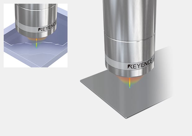
Sheet Thickness Measurement
A sensor is placed above and below a target to measure the thickness of anything in-between. This non-contact method can be used for measuring the thickness of any material and can be used inline or for offline inspection.
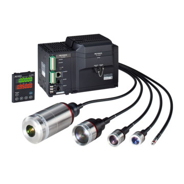
Confocal Displacement Sensor CL-3000 series
Thickness Measurement of a Rubber Sheet
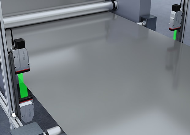
2D thrubeam sensors can measure the step height between a roller and a sheet to get a thickness measurement. Additionally, a second sensor can be added to get a width measurement.
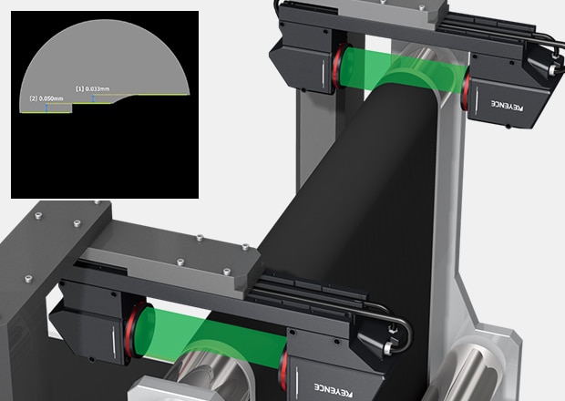

Telecentric Measurement System TM-X5000 series
Confocal Displacement Sensor CL-3000 series
Transparent Sheet Thickness Measurement
Inline thickness measurements can be altered by roller eccentricity, wrinkles, or tension in the sheet. Up to 6 measurement points and 4 layers of clear film can be measured with a single controller.
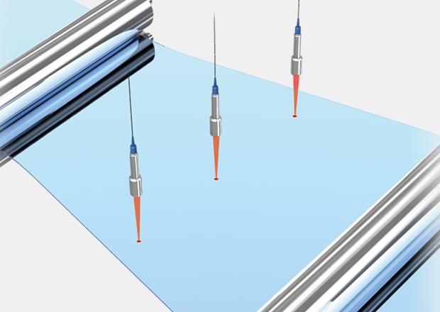

Micro-head Spectral-interference Laser Displacement Meter SI-F series
Confocal Displacement Sensor CL-3000 series
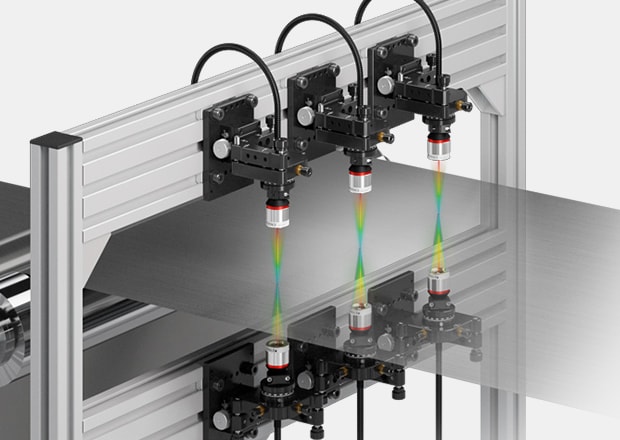
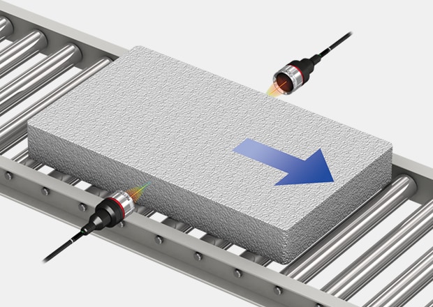
Measurement of Opaque Targets Between Rolls
Thickness is measured by passing a target between two sensor heads.
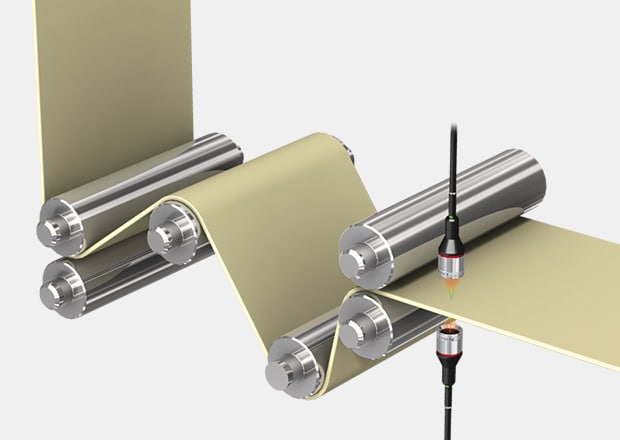
Confocal Displacement Sensor CL-3000 series
Micro-head Spectral-interference Laser Displacement Meter SI-F series
Measurement of Opaque Targets Between Top and Bottom Surfaces
Thickness is measured by passing a target between two sensor heads.
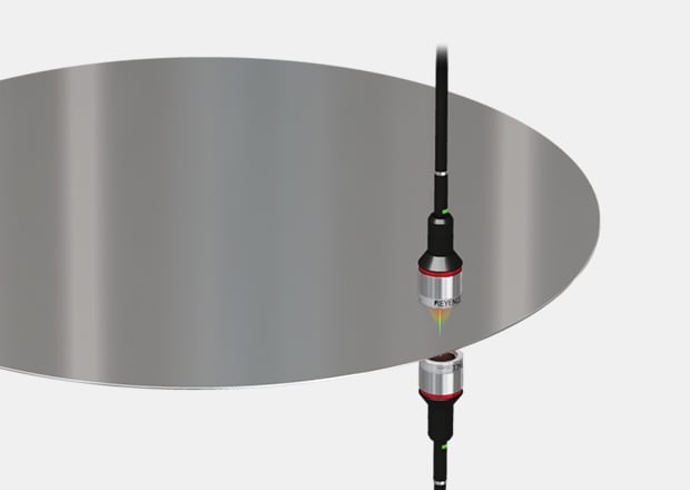
Confocal Displacement Sensor CL-3000 series
Micro-head Spectral-interference Laser Displacement Meter SI-F series
Case Thickness Measurement
Opposing 2D profilers can scan multiple points of thickness over a part. This allows stable thickness measurement even on rough surfaces.
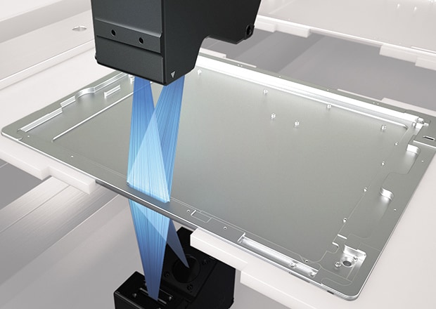
2D/3D Laser Profiler LJ-X8000 series
Thickness Measurement of a Coating Film
Measure transparent films and coatings with a single displacement sensor. Confocal sensors give an accurate thickness measurement from one side of transparent targets.
Confocal Displacement Sensor CL-3000 series
Micro-head Spectral-interference Laser Displacement Meter SI-F series
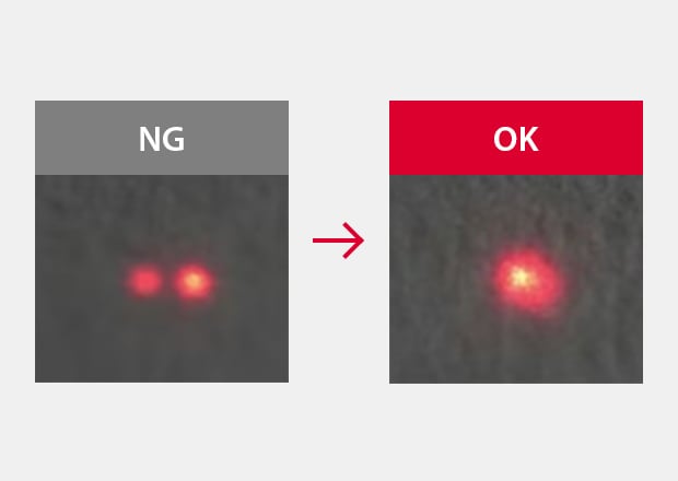
Paste Thickness Measurement After Metal Masking
Conventionally, a vision sensor was used for OK/NG judgment based on the area. Since the LJ-X8000 Series can measure the volume and position of paste application, it can reduce material costs and support higher component densities.
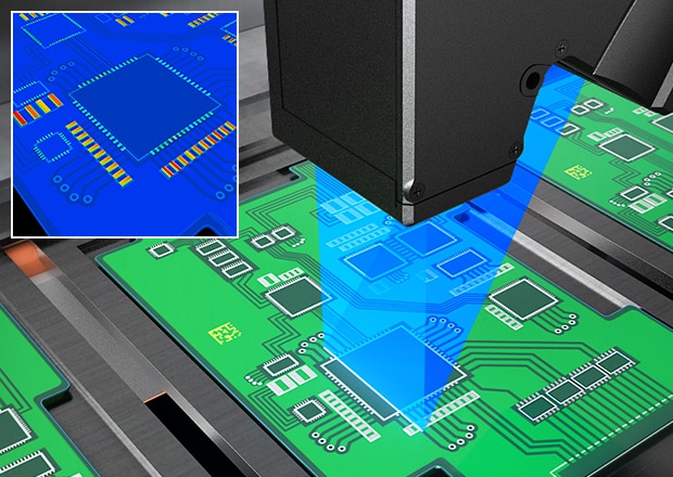
2D/3D Laser Profiler LJ-X8000 series
Measurement of Opaque Targets Using Height Difference From Reference
Thickness is found by simultaneously measuring the base surface and target using a 2D laser displacement sensor and measuring step from the obtained profile.
2D/3D Laser Profiler LJ-X8000 series
Confocal Displacement Sensor CL-3000 series
Precautions During Measurement of Thickness Between Two Sensor Heads
About Optical-Axis Alignment
When you measure a workpiece between two sensor heads, the measured thickness will not change, in principle, even if the workpiece vibrates up and down.
However, if the optical axes of the two sensor heads are not aligned with each other into a straight line, measurement errors may be caused due to the workpiece vibrating up and down or bending. Pay attention to the following points and arrange the installation so that the optical axes can be aligned.
Set the sensor heads so that the centers of the laser spots are aligned even if the target is moved up and down.
- 1) To minimize the effect of the optical axes being misaligned, install sensor heads close to the rollers and select a location where the workpiece tension is stable and the distance from one roller to the next is small. This makes it possible to perform measurements with small amounts of workpiece bending and vibration.
- 2) Orient the sensor heads so that the directions of the projected and received light are perpendicular to the direction of movement of the workpiece, as shown in the figure. This makes it difficult for the sensor heads to be affected by tilting and shaking in the workpiece's direction of movement due to vibration during transportation.
- 3) During optical-axis alignment, measure a thin white plate of resin or a piece of paper as the temporary measurement target. When you measure these targets, the laser spots pass through the target and can be seen. Install the sensor heads so that the spots on the front and back of the target are always aligned even if the target is moved up and down.
Precautions During Thickness Measurement Above a Roller
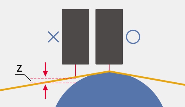
About the Gap Between the Roller and the Workpiece
Thickness is measured by the difference in height when the target is wound around (i.e. held in close contact against) the roller with the roller surface taken as the zero point. If the sensor head isn't perfectly aligned above the roller, measurement errors may be caused due to vibration or bending.
- 1) Apply as much tension to the workpiece as possible. If the tension is weak, the workpiece will not be in full contact with the roll, so a gap ranging from a few micrometers to some tens of micrometers will occur. We recommend that you perform measurements with a tension of 50 N or more applied, but be sure to consider the tensile strength of the workpiece. Perform measurements from a location in which the workpiece tension is as stable as possible, the distance from one roller to the next is small, and the workpiece is positioned on top of the roller.
-
2)
Align the optical axis with the peak position of the roller. As shown in the figure, if the optical axis is misaligned from the peak position of the roller, a measurement error (gap Z) occurs.
Install a mechanism that makes it possible to fine-tune the sensor head position in the feed direction.
Perform measurements on a roll with a large diameter to minimize gap Z even if the optical axis is misaligned from the peak position of the roll.
You will have to make modifications such as those listed here.
About Roller Eccentricity
When a roller rotates, measurement errors may be created due to the eccentricity of the roller. Pay attention to the following points to cancel the influence of roller eccentricity.
- 1) When the locations used to measure the thickness are both edges of the workpiece, measure both the roller surface and the workpiece surface at the same time to find the thickness from the step value.
- 2) When measuring a workpiece on a roller with the roller as the reference, you can perform measurements at the same rotation angle (position) to cancel the influence of eccentricity even if the roller moves in an eccentric manner.
Why Is Measuring Film or Sheet Thickness Often Difficult?
Difficulties in measuring film or sheet thickness are often associated with how thin the material actually is. Ultra-thin materials often used in electronics or packaging industries can be challenging to measure accurately as they deform and compress during measurement. These films and sheets are often very flexible, which makes it even more difficult to measure without affecting them physically.
This is why non-contact measurement methods (like laser displacement sensors) are needed.

What Is Width Measurement?
Width measurement is an important part of dimensional control and is very similar to thickness measurement. That said, width is typically associated with the horizontal dimension of an object (typically at its widest point).
Width measurement sensors are often used to monitor products on assembly lines and ensure they conform to specified dimensions.
When selecting sensors to measure thickness or width, the first step is to choose a method. The target's material, color, and location will all play factors in which option is the best fit for your application. You can browse through the most common setups below or request a free consultation with a local measurement expert.
How to Measure Width
Width is the horizontal dimension of an object, topically referring to the object’s widest points. Width measuring devices ensure that the part or assembly adheres and conforms to specified dimensions while also allowing manufacturing industries to maintain a uniform width across multiple items.
Being the widest possible measurement, a tape measure or a ruler is typically used to measure width for quick, everyday measurements. However, more precision-demanding applications might turn to a width measurement tool like calipers, laser scanners, or even width sensors.
Find the best measurement method and the right equipment to measure "Width."
Film Width Measurement
With two thrubeam micrometers installed on either side of a film, we can get a width measurement and give film position, regardless of color or material.

High-speed optical micrometer LS-9000 series
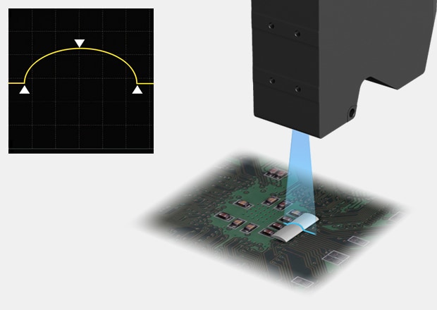
Coating Inspection of Sealing Material
2D Profilers give width, height, and volume of sealant beads inline without touching the part.
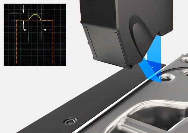
2D/3D Laser Profiler LJ-X8000 series
Confocal Displacement Sensor CL-3000 series
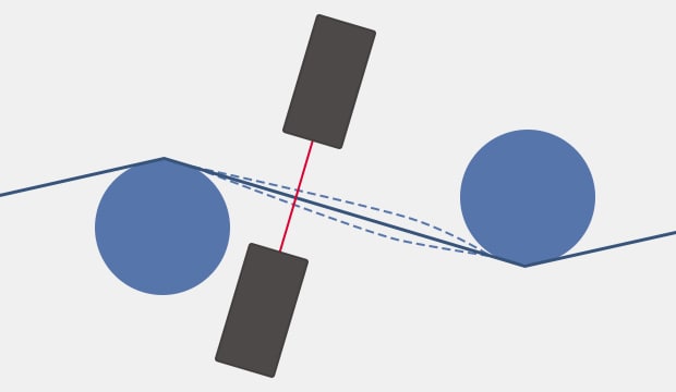
Measurement of Wide Targets
Width is measured by passing a target between two sensor heads.
The end face of the target must be an area wider than the measurement spot. Optical-axis alignment or span adjustment are important to ensure that A+B is fixed even if there is workpiece run-out to the left or right.
Confocal Displacement Sensor CL-3000 series
Micro-head Spectral-interference Laser Displacement Meter SI-F series
Want to maximize the accuracy and efficiency of your measurement systems? Look no further than KEYENCE!

Related Downloads
![Measurement Application Guide [Thickness/Width Measurement]](/img/asset/AS_46768_L.jpg)


![Suggestions for Improved Measurement and Inspection [Thickness Measurement Edition]](/img/asset/AS_89860_L.jpg)
