TM-X Navigator
TM-X Navigator is a PC application for the TM-X5000 Series.
Connecting TM-X Navigator to the controller enables the same operations to be performed as the dedicated display.
In addition, by using the simulator function, the controller measurement content can be simulated on a PC and measurement settings can be created and/or changed.

- Connect to the controller (terminal function)
Clicking this button connects the application to the controller.
For details about operations after the application is connected, refer to  “Basic Operation”.
|
|
[Measurement Result Output] is a function only available on TM-X Navigator (it is not available on the dedicated display). |

- Simulator
Clicking this button displays the list of workspaces and starts the selected workspace simulator.
New workspaces can be created and controller settings can also be transferred (uploaded, downloaded, imported, and exported).
|
|
To download settings from the controller, first delete the reference images for the Program numbers to be downloaded to the workspace. |
- Connection
Configure the settings to connect to the controller (USB or Ethernet).
To connect via Ethernet, specify the controller IP address and port number.
- Language
Select the language to be displayed on TM-X Navigator and the simulator.
- Update
Updates the controller firmware.
To use TM-X Navigator, the environment must meet the requirements shown below.
Main PC system specifications
|
Supported operating systems |
Microsoft Windows 10 Home/Pro/Enterprise, Windows 11 Pro
|
|
Free hard disk space |
2 GB or more (an area for saving image data is required separately) |
|
Display resolution |
Minimum: 1366 × 768 pixels or higher; recommended: 1920 × 1080 pixels or higher |
|
|
|

Installation method
Run the TM-X Navigator installation file (setup.exe) downloaded from the TM-X5000 Series user’s support site (www.keyence.com/tmxus) and follow the instructions displayed on the screen.
|
|
|
To use the simulator function, the activation code issued by KEYENCE is required.
The procedure to obtain the activation code is as follows.
- Click [Simulator] to start the simulator.
The [Input activation code] dialog box will appear.
- Take note of the displayed user ID (8-digit alphanumeric characters) and save it. It will be required for input later.
|
|
Clicking the [Copy] button enables the user ID to be copied. |
- Access the simulator use registration (activation code issuance) page from the TM-X5000 Series user’s support site (www.keyence.com/tmxus).
|
|
To issue a request for the activation code, perform the user registration on the KEYENCE website. |

- Enter the user ID displayed in step 2 into the [User ID] field, and then click [Next].
KEYENCE will send an “Activation code” to the registered email address within one business day.
- Enter the activation code in the activation code input screen.
|
|
|

|
|
To prevent input errors, copy and paste the activation code from the e-mail that is received. |
Start the Simulator
- Click [Simulator]. Select the workspace displayed on the screen, and then click [Start simulator].
The main screen and image strip start.
- Drag the images to be simulated to the image strip and enter a trigger from the trigger buttons to run a simulation.
|
|
Omitted images (1/X omissions) can also be loaded and used in simulations. If an omitted image is used for measurement, the values will not match the measured values of the original image. |

Differences Between the Controller and Simulator
Useful functions unique to the simulator
Special trigger functions
Image strip trigger buttons and trigger input on the keyboard can be used, which are unique triggers to the simulator.
Image strip
 First execute button
 Last execute button
 Reverse execute button
 Forward execute button
 Re-execute button
 Continuous trigger button
Keyboard
|
Forward execution trigger |
Press the “T” key. |
|
Reverse execution trigger |
Press the “F” + “T” keys (Press the “F” key while pressing the “T” key.) |
|
Re-execute trigger |
Press the “S” + “T” keys. (Press the “S” key while pressing the “T” key.) |
|
Cycle execution trigger |
Press the “T” key for 0.3 seconds or longer. |
|
|
Clicking a thumbnail on the image strip also enables execution. |
Differences between the controller and simulator
Measurement time/capture time
As the hardware configuration is not the same on the PC and controller, the measurement time is different even for the same process.
Difference in measurement results
Due to the differences in the computing hardware on the PC and controller, there may be differences in the measurement results.
Differences in head settings
- The head settings will not function.
- In Run mode, the internal trigger does not operate.
- When executing from the image strip, the trigger interval can be set independently in [Trigger interval settings] (set by right-clicking the image strip).
Although other items can be set, the operation differs from the controller.
Program Operation
- When Programs are copied, the images registered on the image strip are also automatically copied.
- Programs cannot be backed up nor restored.
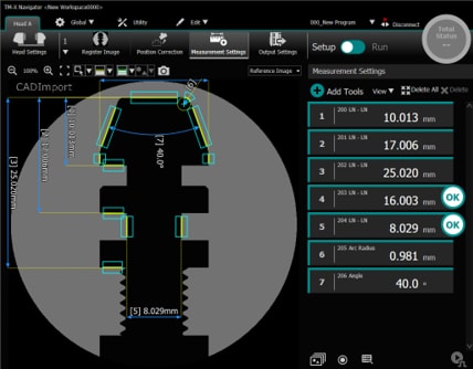
- CAD data (DXF files) can be loaded using [CAD Import] to create Programs.
Display of system information
Only the controller version, serial number, MAC address, and connection device details (version and serial numbers) are displayed.
Output of images and image processing results
Output is not possible to any devices other than the SD card and USB HDD.
Items that cannot be set
- Date/time
Items that cannot be used
- Reboot
- Communication commands for control
Folder configuration on the PC
The folder configuration on the PC when using the TM-X Navigator simulator is shown below.

*1 Stores head-to-head adjustment data when using head-to-head adjustment.
*2 The tolerance table is stored if the tolerance table is saved with the screw tool.
*3 Connecting to the controller with TM-X Navigator and clicking the  button generates the “capture” folder and saves the screen image.
|
|
To use the simulator function, an environment must be created in which the simulator operates on the PC. This is called a “Workspace” and the folder that stores the workspace is called a “Base path”. |
CAD data (DXF files) can be loaded to create Programs that include CAD elements.
|
|
|
- Select [Program Operation] → [CAD Import].
|
|
When two heads are connected, data is imported to the connected head. To import to a different head, select the other head, and select [CAD Import]. |

- Open the CAD data (DXF file) to be loaded.
- Perform [Range] and then click [Next].
Specify the region to be captured (view range) from the CAD data.


- Perform [Create image] and then click [Next].

- Perform [Generate elements] and then click [Complete].
|
|
If [Import CAD contour data] is set to ON, the CAD contour data will be used as the reference for the [Master Difference (Contour)] and [Profile] tools. |

The CAD data (DXF file) is imported.