Chapter 1 Preparation for Use
System Configuration
|
|
It will be 30m with the following connection; “Controller” ‒ “CB-C10R (10m)” ‒ “TM-CX10U (Repeater)” ‒ “CB-C10RX(10m)” ‒ “TM-CX10U (Repeater)” ‒ “CB-C10RX (10m)” ‒ “Receiver head”
|

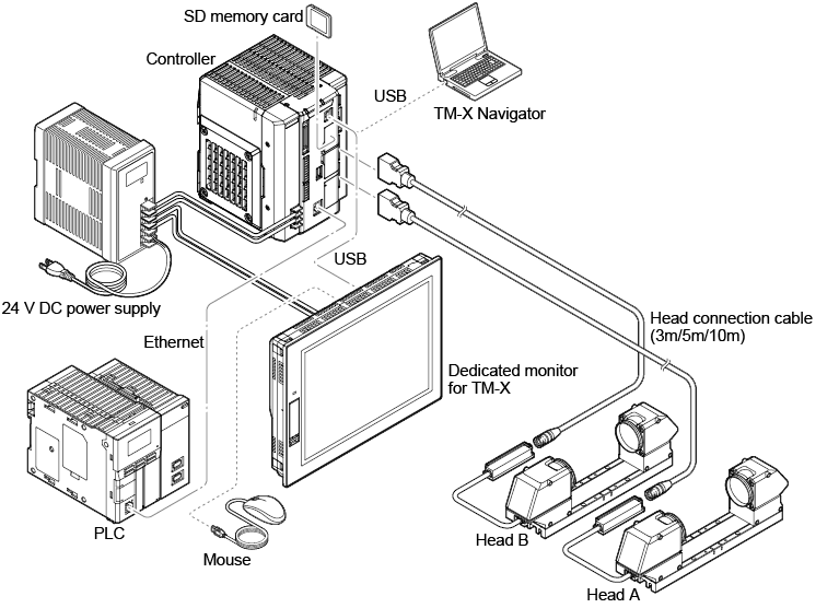
System configuration example 1
|
|
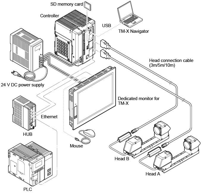
When using a USB cable, either the dedicated monitor for TM-X or the PC (TM-X Navigator) will be connected to the controller. |

System configuration example 2
Part Names and Functions
Controller (TM-X5000)

|
No |
Name |
Function |
||
|
1 |
POWER LED |
Lights green when power is supplied to this unit. |
||
|
2 |
ERROR LED |
Indicates the operating state of the controller.
|
||
|
3 |
RS-232C port |
The port to connect RS-232C cable. (OP-26487: 2.5 m, sold separately) |
||
|
4 |
Simple monitor output (RGB output) |
The simple screen is output only in the Run mode. |
||
|
5 |
Head B port |
The port used to connect the second sensor head cable to the controller. |
||
|
6 |
Head A port |
The port used to connect the sensor head cable to the controller.
|
||
|
7 |
USB connector |
The connector used to connect the USB cable. |
||
|
8 |
SD2 slot |
Insert the SD memory card. (for storing inspection settings and measurement data) |
||
|
9 |
SD1 slot |
Insert the SD memory card. (for storing inspection settings and environmental settings) The supplied SD memory card (CA-SD1G : 1GB) is inserted as SD card 1.
|
||
|
10 |
USB HDD port |
Connect USB 3.0 or USB 2.0 compatible HDD.
If there are concerns about the potential difference with the connections, then use a USB HDD which supports bus-powered drives.
|
||
|
11 |
Ethernet port |
Use to connect an Ethernet cable. |
||
|
12 |
Parallel I/O connector |
Parallel I/O interface (40 pins) used for signal input/output. |
||
|
13 |
Output terminal |
Terminal for signal output (9-pin). |
||
|
14 |
Input terminal |
Terminal for signal input (6-pin). |
||
|
15 |
Power and ground terminals |
Used to connect power (24 VDC) and the ground wire to the system. |
||
|
16 |
Communication expansion unit connector (right side) |
Used to connect the communication expansion unit. |

Head (TM-X5006 / TM-X5040 / TM-X5065/ TM-X5120)
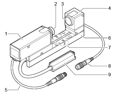
TM-X5006
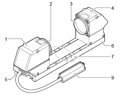
TM-X5040 / TM-X5065 / TM-X5120
|
No |
Name |
Function |
|
1 |
Receiver head |
The part that receives the light from the Transmitter head. |
|
2 |
Receiver cover glass |
Protects the inside of the receiver head. |
|
3 |
Transmitter cover glass |
Protects the inside of the transmitter head. |
|
4 |
Transmitter head |
The part that emits the light for measurement. |
|
5 |
Transmitter-to-receiver cable |
|
|
6 |
Transmitter/receiver base |
Attach and fix the transmitter head and the receiver head. |
|
7 |
Focus mark |
The measurement range in the light transmitting to receiving direction is shown when the head is attached to the transmitter/receiver base. |
|
8 |
Transmitter-to-receiver cable |
Connect to the transmitter-to-receiver cable of the receiver head. (TM-X5006 only) |
|
9 |
Cable box |
(Other than TM-X5120)
|
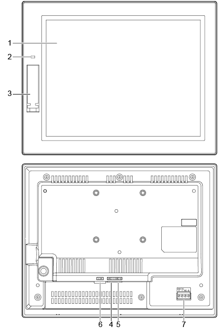
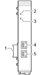
Dedicated monitor for TM-X (TM-MP120)
|
No |
Name |
Function |
|
1 |
Display |
Displays the screen image output from the controller. |
|
2 |
POWER indicator |
Light illuminates when power is input. (Green) |
|
3 |
USB |
Connect a controller or mouse. |
|
4 |
||
|
5 |
||
|
6 |
LAN |
Used when connecting to the controller via Ethernet.
|
|
7 |
Power and ground terminals |
Used to connect power (24 VDC) and the ground wire to the system. |
Communication Expansion Unit (CB-NEC20E/CB-NEP20E/CB-NPN20E)
|
|
The communication expansion unit can be used with the controller of Ver.1.2.****. |
EtherCAT Unit (CB-NEC20E: Optional)
|
No |
Name |
Function |
||
|
1 |
Connector on controller side |
Install the communication expansion unit on the right-hand side of the controller.
|
||
|
2 |
RUN indicator (RUN) |
This indicates the state of EtherCAT communication (green). On: In the OPERATIONAL state. PDO and mailbox communications are functioning normally.
*1: The light goes on for 0.2 seconds and then turns off for 1 second repeatedly. *2: The light goes on for 0.2 seconds and then turns off for 0.2 seconds repeatedly. |
||
|
3 |
ERR indicator (ERR) |
This indicates an error in EtherCAT communication (red).
*1: The light goes on for 0.2 seconds, turns off for 0.2 seconds, turns on for 0.2 seconds, and then turns off for 1 second repeatedly. *2: The light goes on for 0.2 seconds and then turns off for 0.2 seconds repeatedly.
|
||
|
4 |
IN port |
Used to connect the LAN cable. |
||
|
5 |
OUT port |
Used to connect the LAN cable. |
EtherNet/IP Unit (CB-NEP20E: Optional)
|
No |
Name |
Function |
||
|
1 |
Connector on controller side |
Install the communication expansion unit on the right-hand side of the controller.
|
||
|
2 |
Network Status LED (NS) |
This indicates the state of the EtherNet/IP communication.
|
||
|
3 |
Module Status LED (MS) |
Indicates the state of the communication expansion unit.
|
||
|
4 |
P1 port |
Used to connect the LAN cable. |
||
|
5 |
P2 port |
Used to connect the LAN cable. |
PROFINET Unit (CB-NPN20E: Optional)
|
No |
Name |
Function |
||
|
1 |
Connector on controller side |
Install the communication expansion unit on the right-hand side of the controller.
|
||
|
2 |
Network Status LED (NS) |
This indicates the state of the PROFINET communication.
|
||
|
3 |
Module Status LED (MS) |
Indicates the state of the communication expansion unit.
The communication expansion unit is in the Exception state.
The firmware is updating. Do not turn off the power to this device. Turning off the power during this phase may damage the device. |
||
|
4 |
P1 port |
Used to connect the LAN cable. |
||
|
5 |
P2 port |
Used to connect the LAN cable. |
List of Optional Products
|
Name |
Model |
Description |
|
Dedicated mouse |
OP-87506 |
Connects to the dedicated monitor (TM-MP120). |
|
Dedicated monitor mount |
OP-87262 |
Installation mount for the dedicated monitor (TM-MP120). |
|
Connector extension cable |
OP-51657 |
Cable (40 pins) for the parallel I/O interface. |
|
RS-232C communications cable |
OP-26487 |
A communications cable (6 pole, 6 core, 2.5 m) for RS-232C. |
|
RS-232C connector |
OP-26486 |
D-sub 9-pin connector (female) for RS-232C. |
|
USB 2.0 cable |
OP-35331 |
A USB cable (3 m) used to connect to the dedicated monitor or PC (TM-X Navigator). |
|
Ethernet cable |
OP-66843 |
An Ethernet cable (3 m) used to connect to an external device such as the dedicated monitor, PC (TM-X Navigator), or PLC. |
|
SD memory card |
CA-SD16G |
SD memory card (16 GB: Industrial specification) |
|
CA-SD4G |
SD memory card (4 GB: Industrial specification) |
|
|
CA-SD1G |
SD memory card (1 GB: Industrial specification) |
|
|
Protective cover |
OP-88575 |
Protective cover for the TM-X5040. Screws in to the transmitter head and the receiver head.
|
|
OP-88576 |
Protective cover for the TM-X5065. Screws in to the transmitter head and the receiver head.
|
|
|
OP-88775 |
Protective cover for the TM-X5120. Screws in to the transmitter head and the receiver head.
|
|
|
Transmitter-to-receiver cable |
OP-87033 |
An extension cable (1 m) that connects the transmitter head and receiver head. |
|
OP-87034 |
An extension cable (3m) that connects the transmitter head and receiver head. |
