Chapter 5 I/O Control and Timing Charts
List of Communication Commands for Control
Notes on Command Input/Output
When using non-procedural commands
Command input during operation
- Command input is accepted during operation. However, if commands need to be executed in a high-speed operation line, remember that execution of commands may suspend trigger acceptance.
- The execution time of a command depends on the amount of load on the controller and the type of operation performed by the controller. For the use in which a program must wait for command execution to be completed before starting the next inspection, be careful of the waiting time fluctuation according to the conditions mentioned above.
Number of characters for command parameters
Any number of parameter characters within the range specified for each command can be entered.
When an error occurs upon command acceptance
An error response “ER, **, nn” will be returned.
The error response consists of the following information:
|
** |
Received command that caused the error |
|
nn |
2-digit error code
|
An example of error output
When the No. 1005 (unavailable number) is specified for program No. changing command (PW), “ER,PW,22” is returned as response data.
When using number-specified commands
Specification and execution of each command number is processed in 1 word.
Command input during operation
Command input is accepted during operation. However, if commands need to be executed in a high-speed operation line, remember that execution of commands may suspend trigger acceptance.
When an error occurs upon command acceptance
The error code is written in the command result address as the execution result. The error response consists of the following information:
|
0 |
Success |
|
02 |
Command error (The received command is invalid.) |
|
03 |
Command action disabled (The received command cannot work.) |
|
22 |
The number or range of the parameter is incorrect. |
An example of error output
When the No. 1005 (unavailable number) is specified for program No. changing command, “22” is written in the command result address as binary data of 1 word.
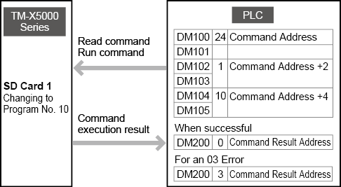
Example: Changing the current program No. to program No. 10 stored in SD card 1 using the PLC-Link.
The detailed command assignments for this example is shown below.
List of Operation Modes and Available Input Commands
= Possible
|
Command type |
Function |
Command name (No protocol) |
Command number (Field network) |
I/O terminal command support |
Run |
Setup |
Block*6 |
|
Trigger |
Trigger |
T1 |
1*1 |
×*3 |
|
|
× |
|
System control |
Switch to run mode |
R0 |
8 |
× |
|
|
|
|
Switch to setup mode |
S0 |
9 |
× |
|
|
× |
|
|
Reset |
RS |
10*1 |
×*3 |
|
× |
x |
|
|
Reboot |
RB |
11 |
× |
|
|
x |
|
|
Save Program |
SS |
12 |
|
|
|
x |
|
|
Clear error |
CE |
13*1 |
|
|
|
x |
|
|
Read run/setup mode |
RM |
16 |
× |
|
|
|
|
|
Change inspection program |
Change inspection programs |
PW |
24 |
|
|
|
x |
|
Read program setting |
PR |
25 |
× |
|
|
x |
|
|
Measurement control |
Change recipe |
EXW |
41*2 |
|
|
|
x |
|
Read recipe |
EXR |
42 |
× |
|
|
x |
|
|
Timing |
TIM |
52*1 |
*4 |
|
|
x |
|
|
Auto zero |
ZR |
53*1 |
*4 |
|
|
x |
|
|
Reset measured value |
MRS |
54*1 |
*4 |
|
|
x |
|
|
Reset measured value (all templates) |
RSA |
55*1 |
*4 |
|
|
x |
|
|
I/O control |
Enable/Disable Trigger Input |
TE |
56 |
×*3 |
|
|
x |
|
Enable/Disable Output |
OE |
57 |
×*3 |
|
× |
x |
|
|
Utility |
Replace the externally specified string |
STW |
60 |
x |
|
|
x |
|
Read the externally specified string |
STR |
61 |
x |
|
|
x |
|
|
Clear Archived Image |
HC |
66 |
× |
|
|
x |
|
|
Change Output File/Folder |
OW |
69 |
|
|
× |
x |
|
|
Echo |
EC |
- |
× |
|
|
|
|
|
System |
Write Date & Time |
TW |
80 |
× |
|
|
x |
|
Read Date & Time |
TR |
81 |
× |
|
|
x |
|
|
Read version information |
VI |
82 |
× |
|
|
|
|
|
Write time zone |
TZW |
83 |
× |
|
× |
x |
|
|
Read time zone |
TZR |
84 |
× |
|
× |
x |
|
|
Fetch measurement results |
Fetch internal measurement values |
GR |
104 |
× |
|
× |
x |
|
Fetch measured values |
GM |
112 |
× |
|
× |
x |
|
|
Head-to-head Adjustment Execution |
Head-to-head Adjustment Execution |
HAE |
122 |
× |
× |
*5 |
x |
|
Image Composition |
Write image composition capture cycle |
ICCW |
128 |
x |
x |
|
x |
|
Read image composition capture cycle |
ICCR |
129 |
x |
|
|
x |
|
|
Simple Monitor View |
Change simple monitor view strings |
AIW |
- |
x |
|
|
x |
|
Obtain simple monitor view strings |
AIR |
- |
x |
|
|
x |
|
|
Setting change |
Write tool settings |
TSW |
130 |
x |
x |
|
x |
|
Read tool settings |
TSR |
131 |
x |
|
|
x |
|
|
Clear tool settings |
TSC |
132 |
x |
x |
|
x |
|
|
Head Adjustment |
Obtain optical axis state |
OASR |
136 |
x |
x |
|
x |
*1 In addition to running commands, functions can also be run by operating a bit device with assigned commands.
*2 Recipe numbers can also be changed by changing the recipe number area for the word device.
*3 Can be run from the input terminal.
*4 Can also be run from the input terminal.
*5 Execution is only possible after the head-to-head adjustment start command is issued.
*6 When switching to setup mode with another device, the commands from the previous device will be “Block”.
(Example) The commands from the PLC will be “Block” when using the PLC to control, but then switching [Setup] modes from the dedicated monitor (TM-MP120) or TM-X Navigator.
Trigger
System control
Change inspection program
Measurement control

I/O control

Utility
System
Fetching Measurement Results
Head-to-head Adjustment Execution
Image Composition
Simple Monitor View
Setting change
Head Adjustment
Input/Output and Control Using EtherNet/IP
This system supports communication via EtherNet/IP.
EtherNet/IP is an open communications standard with specifications that are managed by ODVA (Open Device Net Vendor Association, Inc.). Communication is possible with all devices that support it, regardless of the vendor.
The following functions are possible by EtherNet/IP connection.
|
|
EtherNet/IP, PROFINET, EtherCAT, and PLC-Link cannot be used at the same time. |
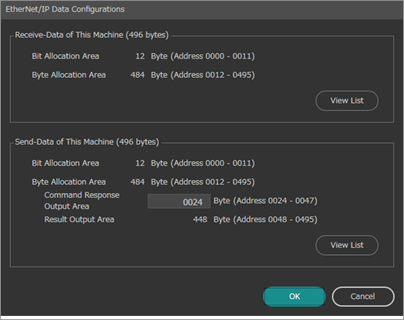
Controller EtherNet/IP Communication Specifications
Allocation Conditions of Cyclic Communication Data
Example of the send-data settings for this controller (TM-X5000 Series to KV-7000 Series)
Example when 1 TM-X5000 series is connected to a KV-7000 Series, cyclic communication data size is 496 bytes (addresses 0000 - 0495), and the command response output area is set to 24 bytes (B****/W**** in the table are examples of KV-7000 link relay and link register address allocation)
|
Setting condition |
Address (byte) |
7bit |
6bit |
5bit |
4bit |
3bit |
2bit |
1bit |
0bit |
||||||||
|
Bit area |
0000 |
B007 |
Reserved |
B006 |
Reserved |
B005 |
Reserved |
B004 |
Result OR |
B003 |
Result Ready |
B002 |
Cmd Ready |
B001 |
Cmd Error |
B000 |
Cmd Complete |
|
0001 |
B00F |
MSR_VALID |
B00E |
RUN |
B00D |
Reserved |
B00C |
ERROR |
B00B |
BUSY |
B00A |
Reserved |
B009 |
TRG_ack |
B008 |
READY |
|
|
0002 |
B017 |
Reserved |
B016 |
Reserved |
B015 |
RESET_ALL_ack |
B014 |
MSR_RESET_ack |
B013 |
ZERO_OFF_ack |
B012 |
ZERO_ON_ack |
B011 |
Reserved |
B010 |
TIMING_ack |
|
|
0003 |
B01F |
Reserved |
B01E |
Reserved |
B01D |
Reserved |
B01C |
Reserved |
B01B |
Reserved |
B01A |
Reserved |
B019 |
Reserved |
B018 |
Reserved |
|
|
0004 |
B027 |
Tool Judge Value7 |
B026 |
Tool Judge Value6 |
B025 |
Tool Judge Value5 |
B024 |
Tool Judge Value4 |
B023 |
Tool Judge Value3 |
B022 |
Tool Judge Value2 |
B021 |
Tool Judge Value1 |
B020 |
Tool Judge Value0 |
|
|
0005 |
B02F |
Tool Judge Value15 |
B02E |
Tool Judge Value14 |
B02D |
Tool Judge Value13 |
B02C |
Tool Judge Value12 |
B02B |
Tool Judge Value11 |
B02A |
Tool Judge Value10 |
B029 |
Tool Judge Value9 |
B028 |
Tool Judge Value8 |
|
|
0006 |
B037 |
Tool Judge Value23 |
B036 |
Tool Judge Value22 |
B035 |
Tool Judge Value21 |
B034 |
Tool Judge Value20 |
B033 |
Tool Judge Value19 |
B032 |
Tool Judge Value18 |
B031 |
Tool Judge Value17 |
B030 |
Tool Judge Value16 |
|
|
0007 |
B03F |
Tool Judge Value31 |
B03E |
Tool Judge Value30 |
B03D |
Tool Judge Value29 |
B03C |
Tool Judge Value28 |
B03B |
Tool Judge Value27 |
B03A |
Tool Judge Value26 |
B039 |
Tool Judge Value25 |
B038 |
Tool Judge Value24 |
|
|
0008 |
B047 |
Tool Judge Value39 |
B046 |
Tool Judge Value38 |
B045 |
Tool Judge Value37 |
B044 |
Tool Judge Value36 |
B043 |
Tool Judge Value35 |
B042 |
Tool Judge Value34 |
B041 |
Tool Judge Value33 |
B040 |
Tool Judge Value32 |
|
|
0009 |
B04F |
Tool Judge Value47 |
B04E |
Tool Judge Value46 |
B04D |
Tool Judge Value45 |
B04C |
Tool Judge Value44 |
B04B |
Tool Judge Value43 |
B04A |
Tool Judge Value42 |
B049 |
Tool Judge Value41 |
B048 |
Tool Judge Value40 |
|
|
0010 |
B057 |
Tool Judge Value55 |
B056 |
Tool Judge Value54 |
B055 |
Tool Judge Value53 |
B054 |
Tool Judge Value52 |
B053 |
Tool Judge Value51 |
B052 |
Tool Judge Value50 |
B051 |
Tool Judge Value49 |
B050 |
Tool Judge Value48 |
|
|
0011 |
B05F |
Tool Judge Value63 |
B05E |
Tool Judge Value62 |
B05D |
Tool Judge Value61 |
B05C |
Tool Judge Value60 |
B05B |
Tool Judge Value59 |
B05A |
Tool Judge Value58 |
B059 |
Tool Judge Value57 |
B058 |
Tool Judge Value56 |
|
|
Error code area |
0012 |
W000 |
Error Code |
||||||||||||||
|
0013 |
|||||||||||||||||
|
Reserved area |
0014 |
W001 |
Reserved |
||||||||||||||
|
0015 |
|||||||||||||||||
|
Measurement count area |
0016 |
W002 |
Total Count |
||||||||||||||
|
0017 |
|||||||||||||||||
|
0018 |
|||||||||||||||||
|
0019 |
|||||||||||||||||
|
Command output area |
0020 |
W004 |
Command Result |
||||||||||||||
|
0021 |
|||||||||||||||||
|
0022 |
|||||||||||||||||
|
0023 |
|||||||||||||||||
|
0024 |
W006 |
Command Data 1 |
|||||||||||||||
|
0025 |
|||||||||||||||||
|
0026 |
|||||||||||||||||
|
0027 |
|||||||||||||||||
|
0028 |
W008 |
Command Data 2 |
|||||||||||||||
|
0029 |
|||||||||||||||||
|
0030 |
|||||||||||||||||
|
0031 |
|||||||||||||||||
|
… |
… |
… |
|||||||||||||||
|
0044 |
W010 |
Command Data 6 |
|||||||||||||||
|
0045 |
|||||||||||||||||
|
0046 |
|||||||||||||||||
|
0047 |
|||||||||||||||||
|
Results output area |
0048 |
W012 |
Result Data 1 |
||||||||||||||
|
0049 |
|||||||||||||||||
|
0050 |
|||||||||||||||||
|
0051 |
|||||||||||||||||
|
0052 |
W014 |
Result Data 2 |
|||||||||||||||
|
0053 |
|||||||||||||||||
|
0054 |
|||||||||||||||||
|
0055 |
|||||||||||||||||
|
… |
… |
… |
|||||||||||||||
Example of the receive-data settings for this controller (KV-7000 Series to TM-X5000 Series)
Example when one TM-X5000 Series model is connected to a KV-7000 Series model and cyclic communication data size is 496 bytes (addresses 0000 - 0495)
(B****/W**** in the table are examples of KV-7000 link relay and link register address allocation)
|
Setting condition |
Address (byte) |
7bit |
6bit |
5bit |
4bit |
3bit |
2bit |
1bit |
0bit |
||||||||
|
Bit area |
0000 |
B067 |
Reserved |
B066 |
Reserved |
B065 |
Reserved |
B064 |
Error reset request |
B063 |
Result ack |
B062 |
Reserved |
B061 |
Reserved |
B060 |
Cmd request |
|
0001 |
B06F |
Reserved |
B06E |
Reserved |
B06D |
Reserved |
B06C |
Reserved |
B06B |
Reserved |
B06A |
Reserved |
B069 |
Reserved |
B068 |
TRG |
|
|
0002 |
B077 |
Reserved |
B076 |
Reserved |
B075 |
Reserved |
B074 |
Reserved |
B073 |
Reserved |
B072 |
TEST |
B071 |
EXT |
B070 |
RESET |
|
|
0003 |
B07F |
Reserved |
B07E |
Reserved |
B07D |
RESET_ALL |
B07C |
MSR_RESET |
B07B |
ZERO_OFF |
B07A |
ZERO_ON |
B079 |
Reserved |
B078 |
TIMING |
|
|
0004 |
B087 |
Reserved |
B086 |
Reserved |
B085 |
Reserved |
B084 |
Reserved |
B083 |
Reserved |
B082 |
Reserved |
B081 |
Reserved |
B080 |
Reserved |
|
|
0005 |
B08F |
Reserved |
B08E |
Reserved |
B08D |
Reserved |
B08C |
Reserved |
B08B |
Reserved |
B08A |
Reserved |
B089 |
Reserved |
B088 |
Reserved |
|
|
0006 |
B097 |
Reserved |
B096 |
Reserved |
B095 |
Reserved |
B094 |
Reserved |
B093 |
Reserved |
B092 |
Reserved |
B091 |
Reserved |
B090 |
Reserved |
|
|
0007 |
B09F |
Reserved |
B09E |
Reserved |
B09D |
Reserved |
B09C |
Reserved |
B09B |
Reserved |
B09A |
Reserved |
B099 |
Reserved |
B098 |
Reserved |
|
|
0008 |
B0A7 |
Reserved |
B0A6 |
Reserved |
B0A5 |
Reserved |
B0A4 |
Reserved |
B0A3 |
Reserved |
B0A2 |
Reserved |
B0A1 |
Reserved |
B0A0 |
Reserved |
|
|
0009 |
B0AF |
Reserved |
B0AE |
Reserved |
B0AD |
Reserved |
B0AC |
Reserved |
B0AB |
Reserved |
B0AA |
Reserved |
B0A9 |
Reserved |
B0A8 |
Reserved |
|
|
0010 |
B0B7 |
Reserved |
B0B6 |
Reserved |
B0B5 |
Reserved |
B0B4 |
Reserved |
B0B3 |
Reserved |
B0B2 |
Reserved |
B0B1 |
Reserved |
B0B0 |
Reserved |
|
|
0011 |
B0BF |
Reserved |
B0BE |
Reserved |
B0BD |
Reserved |
B0BC |
Reserved |
B0BB |
Reserved |
B0BA |
Reserved |
B0B9 |
Reserved |
B0B8 |
Reserved |
|
|
Recipe No. |
0012 |
W0F2 |
ExecCondNo |
||||||||||||||
|
0013 |
|||||||||||||||||
|
0014 |
W0F3 |
Reserved |
|||||||||||||||
|
0015 |
|||||||||||||||||
|
Command input area |
0016 |
W0F4 |
Command number |
||||||||||||||
|
0017 |
|||||||||||||||||
|
0018 |
|||||||||||||||||
|
0019 |
|||||||||||||||||
|
0020 |
W0F6 |
Cmd Parameter1 |
|||||||||||||||
|
0021 |
|||||||||||||||||
|
0022 |
|||||||||||||||||
|
0023 |
|||||||||||||||||
|
0024 |
W0F8 |
Cmd Parameter2 |
|||||||||||||||
|
0025 |
|||||||||||||||||
|
0026 |
|||||||||||||||||
|
0027 |
|||||||||||||||||
|
0028 |
W0FA |
Cmd Parameter3 |
|||||||||||||||
|
0029 |
|||||||||||||||||
|
0030 |
|||||||||||||||||
|
0031 |
|||||||||||||||||
|
… |
… |
… |
|||||||||||||||
|
|
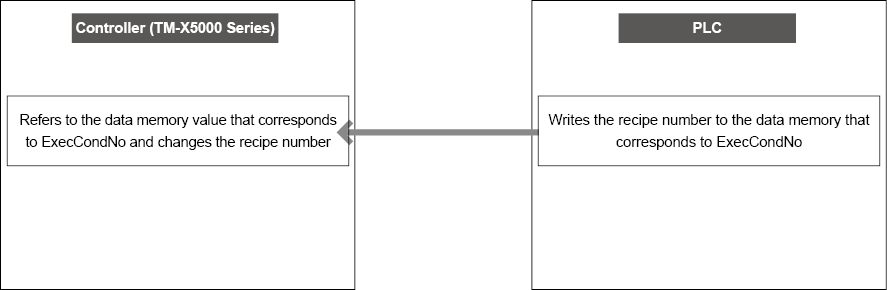
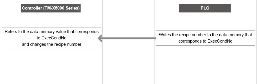
As ExecCondNo is only loaded by the controller when there are changes, the recipe number can also be overwritten by a command. |
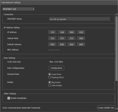
Changing the EtherNet/IP Settings
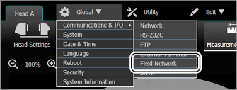
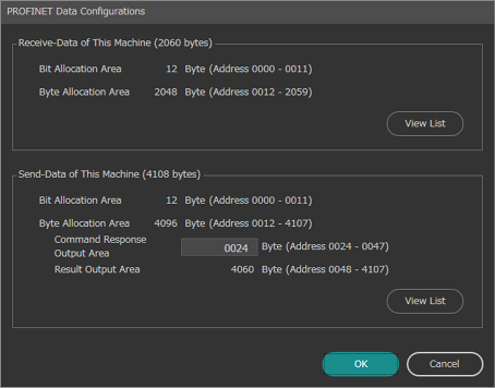
The settings for controlling data input and output via EtherNet/IP can be changed on the [Field Network] screen under [Communications & I/O] in [Global].
|
|
|
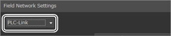
- Select [Global] → [Communications & I/O] → [Field Network].

- Select [EtherNet/IP] or [EtherNet/IP-Unit].
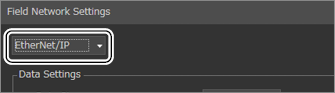
- Change the settings as required.
<When [Ethernet/IP] is selected>

<When [EtherNet/IP-Unit] is selected>
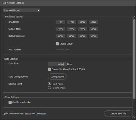
- Click [OK].
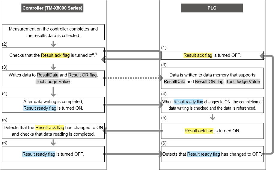
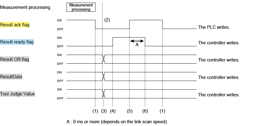
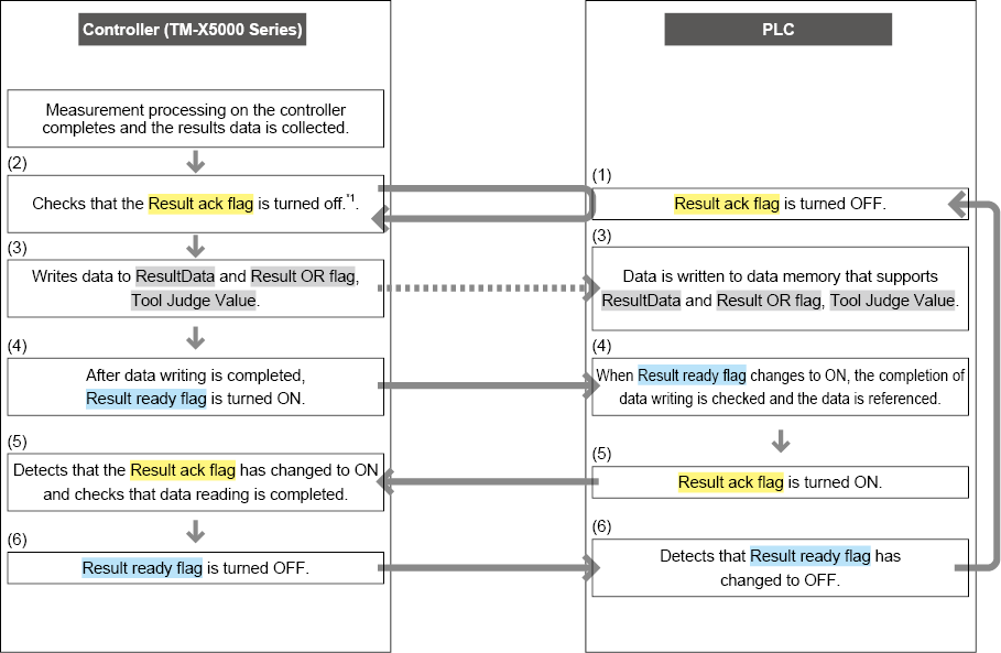
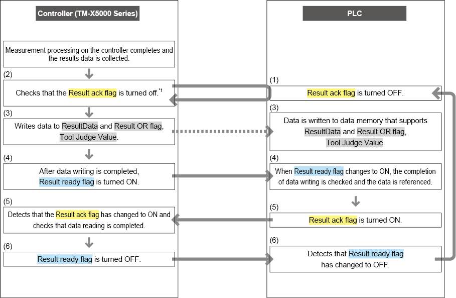
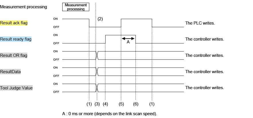
Outputting Measurement Data Using EtherNet/IP Cyclic Communications (Data Output)
Change the output settings for data output using EtherNet/IP.
Data output flow (example of connection with PLC EtherNet/IP unit)
Set the data and address for output in the output settings.
The controller outputs data via EtherNet/IP in the following manner.
|
|
When used with [Hold Mode] set to [ON], selecting [Update Every Timing] (Detail) updates the measurement value by inputting TIMING, ZERO, MSR_RESET, and RESET_ALL (the internal measurement value will not update). |
|
|
|
|
|
*1 When the results output handshake is OFF, output data is overwritten and updated without checking whether the Result ack flag is OFF. To take the rise of Result ready flag as a data reference synchronization signal, turn the Result ack flag ON at each output, which will turn the Result ready flag OFF. |
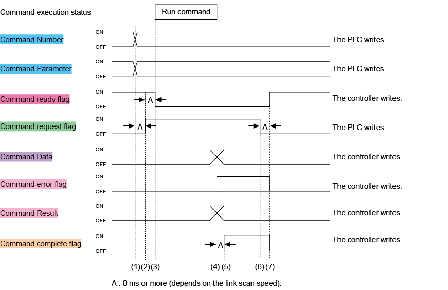
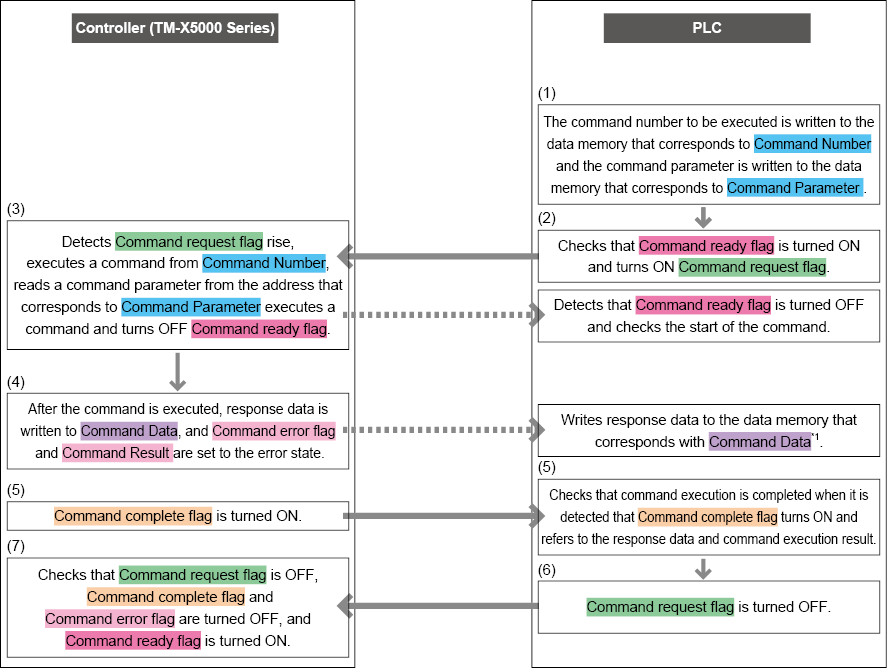
Controlling the Controller with EtherNet/IP Cyclic Communication (Command Control)
The communication control commands can be executed at any time.
Flow of command process using EtherNet/IP (example of connection with PLC EtherNet/IP unit)
The controller performs command control via EtherNet/IP in the following manner.
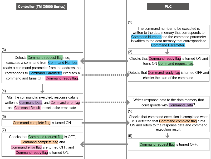
In the case of a command for which there is no response data, data is not output in response to the Command Data.
|
|
When an error occurs, the command execution results are written to Command Result. (0: Success, <Error code>: Failure). The error cords conform to |
Controlling the Controller with EtherNet/IP Cyclic Communication (Change Recipe Number)
The recipe number can be changed at any time.
Workflow to change the recipe number
The controller changes the value of the recipe number using EtherNet/IP as shown below.
The changed value is applied at the next measurement.
Troubleshooting
When correct operation does not occur
Checking whether or not the EtherNet/IP connection is correct
From [Global] for the controller, select [Communications & I/O] - [Field Network], and then check [Cyclic Communication Status:] at the bottom of the screen.
If [Not Connected] is displayed here, communication has failed. Check the cable (cross cable when connected directly), IP address, communications settings on the PLC side, and other items again.
|
|
When connecting to a Rockwell SLC5/05, because cyclic communication is not performed, [Not Connected] is displayed even when the connection is correct. |
Result OR flag is not output.
The “Result OR flag” is updated in coordination with results output with EtherNet/IP as the output destination. When the “Result OR flag” is used, it is necessary to configure the output setting so that 1 or more data item is output via EtherNet/IP.
Result ready flag remains ON and does not change.
There is the possibility that “Result ack flag” control is not being performed correctly. The “Result ready flag” turns OFF when the “Result ack flag” rise is recognized in sending (this controller receiving). This is the same regardless of whether “Enable Handshake” is selected or cleared.
Data cannot be acquired correctly when reading data based on the change in the rise of STO output from an external terminal.
STO is the strobe signal for terminal output. Therefore, it cannot be used as the strobe signal for any other data output.
Refer to the “Result ready flag” for the timing as to when to read data by EtherNet/IP.
Although results data is output beginning from byte address 0048, it is unknown where the data is output to on the PLC (KV Series) side.
With the KV Series, when automatic allocation is used for the first TM-X5000 series, the TM-X5000 series results data is written beginning from link register W0012.
With KV series automatic allocation, allocation byte addresses 0000-0011 are for the link relay (beginning from B0000), and byte addresses beginning from 0012 are for the link register. Allocation begins at the start from W0000, with 1 register used for each 2-byte address.
When the results data byte address is 0048, then (48 - 12)/2 = No. 18→12Hex, and results data is written beginning from W0012.
Error messages
|
Message |
Cause |
Corrective Action |
Error cause No. |
|
EtherNet/IP communication failed. |
Cyclic communication was interrupted. (When recovery is possible, recovery occurs automatically.) |
|
13601 |
|
EtherNet/IP output failed due to a full buffer. |
The controller output buffer for outputting via the EtherNet/IP port is full. |
Change the RPI setting so the data is output via EtherNet/IP at a faster rate than it builds up. Or, extend the time between triggers. Note: Results data are not written when the buffer is full. |
13602 |
|
The delay of the handshake control causes skipping of the EtherNet/IP communication result output. |
When the EtherNet/IP handshake is ON, delayed handshake caused results output via EtherNet/IP to be skipped. |
Change the RPI setting so the data from the tool is output via EtherNet/IP at a faster rate than it builds up. Or, extend the time between triggers. Note: Output does not occur when the output buffer is full. |
13603 |
|
The EtherNet/IP unit cannot be recognized. |
EtherNet/IP unit was not recognized and the controller cannot use EtherNet/IP communication. |
|
13604 |
Communicating with the Controller Using EtherNet/IP Message Communications
For details of the basic communication specifications, refer to  “Controller EtherNet/IP Communication Specifications”.
Object configuration
The controller EtherNet/IP functions include the following objects. These objects can be accessed using message communications.
|
Class (object name) |
Class ID |
Instance ID |
|
Identity Object |
1 (01Hex) |
1 (01Hex) |
|
Message Router Object |
2 (02Hex) |
1 (01Hex) |
|
Assembly Object |
4 (04Hex) |
100 (64Hex): Input |
|
101 (65Hex): Output (when using the controller’s Ethernet port) |
||
|
150 (96Hex): Output (when using the EtherNet/IP unit) |
||
|
Connection Manager Object |
6 (06Hex) |
1 (01Hex) |
|
Measurement Object |
113 (0x71) |
1 (01Hex) |
|
Port Object |
244 (F4Hex) |
1 (01Hex) |
|
TCP/IP Interface Object |
245 (F5Hex) |
1 (01Hex) |
|
EtherNet Link Object |
246 (F6Hex) |
1 (01Hex) |
|
|
|
ClassID : 4 (04Hex) Assembly Object
Description
The same data that is sent and received by cyclic communications can be accessed and controlled directly by message communications.
This can be used to perform control using the same data format as with cyclic communication for models that do not support cyclic communication (such as the Rockwell SLC5/05).
|
|
Be aware that with message communications, it is not possible to perform time-specific control as it is with cyclic communications. |
ClassID: 113 (71Hex) Measurement Object
Description
This object is unique to the controller, and provides the attributes and services that are necessary to control the controller by means of message communications.
For details concerning control by attributes, refer to the control sequence for cyclic communication.
Controlling the Controller Using EtherNet/IP Message Communications
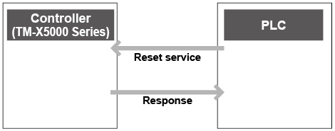
Resetting the controller using EtherNet/IP message communication
Controller measurement can be reset using message communication by means of the Measurement Object reset service.
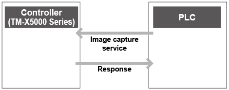
Controlling image capture with EtherNet/IP message communication
Command control with EtherNet/IP message communication

Fetching Measurement Data Using EtherNet/IP Message Communications (Fetch Data)
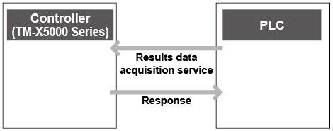
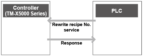
Changing the Recipe Number Using EtherNet/IP Message Communications (Rewrite Recipe No.)
Overview of Control/Data Output Using PROFINET
This system supports communication via PROFINET.
PROFINET is an open communications standard with specifications that are specified by PI (PROFIBUS & PROFINET International) and communications are possible with all devices that support it, regardless of the vendor. This system conforms to ConformanceClass A.
The Ethernet port complies with Conformance Class A and the PROFINET unit (CB-NPN20E: Optional) complies with Conformance Class C.
The following functions are possible with a PROFINET connection.
|
|
EtherNet/IP, PROFINET, EtherCAT, and PLC-Link cannot be used at the same time. |
Controller PROFINET Communication Specifications
Standard specifications
This system’s PROFINET communications supports “periodic communication” and “recorded data communication (aperiodic communication)”.
Allocation Conditions of Periodic Communication Data
Example of the send-data settings for this controller (TM-X5000 Series)
|
Setting condition |
Address (byte) |
7bit |
6bit |
5bit |
4bit |
3bit |
2bit |
1bit |
0bit |
|
Bit area |
0000 |
Reserved |
Reserved |
Reserved |
Result OR |
Result Ready |
Cmd Ready |
Cmd Error |
Cmd Complete |
|
0001 |
MSR_VALID |
RUN |
Reserved |
ERROR |
BUSY |
Reserved |
TRG_ack |
READY |
|
|
0002 |
Reserved |
Reserved |
RESET_ALL_ack |
MSR_RESET_ack |
ZERO_OFF_ack |
ZERO_ON_ack |
Reserved |
TIMING_ack |
|
|
0003 |
Reserved |
Reserved |
Reserved |
Reserved |
Reserved |
Reserved |
Reserved |
Reserved |
|
|
0004 |
Tool Judge Value 7 |
Tool Judge Value 6 |
Tool Judge Value 5 |
Tool Judge Value 4 |
Tool Judge Value 3 |
Tool Judge Value 2 |
Tool Judge Value 1 |
Tool Judge Value 0 |
|
|
0005 |
Tool Judge Value 15 |
Tool Judge Value 14 |
Tool Judge Value 13 |
Tool Judge Value 12 |
Tool Judge Value 11 |
Tool Judge Value 10 |
Tool Judge Value 9 |
Tool Judge Value 8 |
|
|
0006 |
Tool Judge Value 23 |
Tool Judge Value 22 |
Tool Judge Value 21 |
Tool Judge Value 20 |
Tool Judge Value 19 |
Tool Judge Value 18 |
Tool Judge Value 17 |
Tool Judge Value 16 |
|
|
0007 |
Tool Judge Value 31 |
Tool Judge Value 30 |
Tool Judge Value 29 |
Tool Judge Value 28 |
Tool Judge Value 27 |
Tool Judge Value 26 |
Tool Judge Value 25 |
Tool Judge Value 24 |
|
|
0008 |
Tool Judge Value 39 |
Tool Judge Value 38 |
Tool Judge Value 37 |
Tool Judge Value 36 |
Tool Judge Value 35 |
Tool Judge Value 34 |
Tool Judge Value 33 |
Tool Judge Value 32 |
|
|
0009 |
Tool Judge Value 47 |
Tool Judge Value 46 |
Tool Judge Value 45 |
Tool Judge Value 44 |
Tool Judge Value 43 |
Tool Judge Value 42 |
Tool Judge Value 41 |
Tool Judge Value 40 |
|
|
0010 |
Tool Judge Value 55 |
Tool Judge Value 54 |
Tool Judge Value 53 |
Tool Judge Value 52 |
Tool Judge Value 51 |
Tool Judge Value 50 |
Tool Judge Value 49 |
Tool Judge Value 48 |
|
|
0011 |
Tool Judge Value 63 |
Tool Judge Value 62 |
Tool Judge Value 61 |
Tool Judge Value 60 |
Tool Judge Value 59 |
Tool Judge Value 58 |
Tool Judge Value 57 |
Tool Judge Value 56 |
|
|
Error code area |
0012 |
Error Code |
|||||||
|
0013 |
|||||||||
|
Reserved area |
0014 |
Reserved |
|||||||
|
0015 |
|||||||||
|
Measurement count area |
0016 |
Total Count |
|||||||
|
0017 |
|||||||||
|
0018 |
|||||||||
|
0019 |
|||||||||
|
Command output area |
0020 |
Command Result |
|||||||
|
0021 |
|||||||||
|
0022 |
|||||||||
|
0023 |
|||||||||
|
0024 |
Command Data 1 |
||||||||
|
0025 |
|||||||||
|
0026 |
|||||||||
|
0027 |
|||||||||
|
0028 |
Command Data 2 |
||||||||
|
0029 |
|||||||||
|
0030 |
|||||||||
|
0031 |
|||||||||
|
… |
|||||||||
|
0044 |
Command Data 6 |
||||||||
|
0045 |
|||||||||
|
0046 |
|||||||||
|
0047 |
|||||||||
|
Results output area |
0048 |
Result Data 1 |
|||||||
|
0049 |
|||||||||
|
0050 |
|||||||||
|
0051 |
|||||||||
|
0052 |
Result Data 2 |
||||||||
|
0053 |
|||||||||
|
0054 |
|||||||||
|
0055 |
|||||||||
|
… |
… |
||||||||
Example of controller receive-data settings
|
Setting condition |
Address (byte) |
7bit |
6bit |
5bit |
4bit |
3bit |
2bit |
1bit |
0bit |
|
Bit area Reserved area |
0000 |
Reserved |
Reserved |
Reserved |
Error reset request |
Result ack |
Reserved |
Reserved |
Cmd request |
|
0001 |
Reserved |
Reserved |
Reserved |
Reserved |
Reserved |
Reserved |
Reserved |
TRG |
|
|
0002 |
Reserved |
Reserved |
Reserved |
Reserved |
Reserved |
TEST |
EXT |
RESET |
|
|
0003 |
Reserved |
Reserved |
RESET_ALL |
MSR_RESET |
ZERO_OFF |
ZERO_ON |
Reserved |
TIMING |
|
|
0004 |
Reserved |
Reserved |
Reserved |
Reserved |
Reserved |
Reserved |
Reserved |
Reserved |
|
|
0005 |
Reserved |
Reserved |
Reserved |
Reserved |
Reserved |
Reserved |
Reserved |
Reserved |
|
|
0006 |
Reserved |
Reserved |
Reserved |
Reserved |
Reserved |
Reserved |
Reserved |
Reserved |
|
|
0007 |
Reserved |
Reserved |
Reserved |
Reserved |
Reserved |
Reserved |
Reserved |
Reserved |
|
|
0008 |
Reserved |
Reserved |
Reserved |
Reserved |
Reserved |
Reserved |
Reserved |
Reserved |
|
|
0009 |
Reserved |
Reserved |
Reserved |
Reserved |
Reserved |
Reserved |
Reserved |
Reserved |
|
|
0010 |
Reserved |
Reserved |
Reserved |
Reserved |
Reserved |
Reserved |
Reserved |
Reserved |
|
|
0011 |
Reserved |
Reserved |
Reserved |
Reserved |
Reserved |
Reserved |
Reserved |
Reserved |
|
|
Recipe No. |
0012 |
ExecCondNo |
|||||||
|
0013 |
|||||||||
|
0014 |
Reserved |
||||||||
|
0015 |
|||||||||
|
Command input area |
0016 |
Command number |
|||||||
|
0017 |
|||||||||
|
0018 |
|||||||||
|
0019 |
|||||||||
|
0020 |
Cmd Parameter1 |
||||||||
|
0021 |
|||||||||
|
0022 |
|||||||||
|
0023 |
|||||||||
|
0024 |
Cmd Parameter2 |
||||||||
|
0025 |
|||||||||
|
0026 |
|||||||||
|
0027 |
|||||||||
|
0028 |
Cmd Parameter3 |
||||||||
|
0029 |
|||||||||
|
0030 |
|||||||||
|
0031 |
|||||||||
|
… |
|||||||||
|
|
As ExecCondNo is only loaded by the controller when there are changes, the recipe number can also be overwritten by a command. |
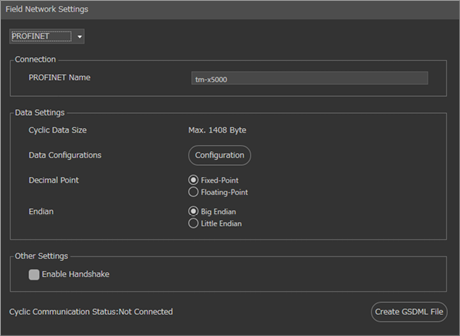
Changing PROFINET Settings
The settings for controlling data input and output via PROFINET can be changed on the [Field Network] screen under [Communications & I/O] in [Global].
|
|
|
- Select [Global] → [Communications & I/O] → [Field Network].
- Select [PROFINET] or [PROFINET-Unit].

- Change the settings as required.
<When [PROFINET] is selected>
<When [PROFINET-Unit] is selected>
- Click [OK].
Outputting Measurement Data Using PROFINET Periodic Communications (Data Output)
Change the output settings for data output using PROFINET.
Data output flow (example of connection with PLC PROFINET unit)
Set the data and address for output in the output settings.
The controller outputs data via PROFINET in the following manner.
|
|
When used with [Hold Mode] set to [ON], selecting [Update Every Timing] (Detail) updates the measurement value by inputting TIMING, ZERO, MSR_RESET, and RESET_ALL (the internal measurement value will not update). |
|
|
|
|
|
*1 When the results output handshake is OFF, output data is overwritten and updated without checking whether the Result ack flag is OFF. To take the rise of Result ready flag as a data reference synchronization signal, turn the Result ack flag ON at each output, which will turn the Result ready flag OFF. |

Controlling the Controller with PROFINET Periodic Communication (Command Control)
The communication control commands can be executed at any time.
Flow of Command Process using PROFINET (Example of Connection with the PLC’s PROFINET Unit)
The controller performs command control via PROFINET in the following manner.
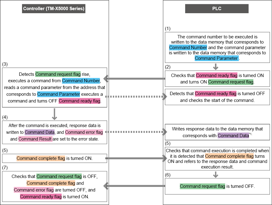
In the case of a command for which there is no response data, data is not output in response to the Command Data.
|
|
When an error occurs, the command execution results are written to Command Result. (0: Success, <Error code>: Failure). The error cords conform to |
Controlling the Controller with PROFINET Cyclic Communication (Change Recipe Number)
The recipe number can be changed at any time.
Workflow to change the recipe number
The controller changes the value of the recipe number using PROFINET as shown below.
The changed value is applied at the next measurement.
Troubleshooting
When correct operation does not occur
Checking whether or not the PROFINET connection is correct
From [Global] for the controller, select [Communications & I/O] [Field Network], and then check [Periodic Communication Status:]. If [Not Connected] is displayed here, communication has failed. Check the cable connection, IP address, and communications settings on the PLC again.
Result OR flag is not output.
The Result OR flag is updated in coordination with results output with PROFINET as the output destination. When the “Result OR flag” is used, it is necessary to configure the output setting so that one or more data item is output via PROFINET.
Result ready flag remains ON and does not change.
There is the possibility that “Result ack flag” control is not being performed correctly. The “Result ready flag” turns OFF when the “Result ack flag” rise is recognized in sending (this controller receiving). This is the same regardless of whether “Enable Handshake” is selected or cleared.
Data cannot be acquired correctly when reading data based on the change in the rise of STO output from an external terminal.
STO is the data strobe signal for terminal output. Therefore it cannot be used as the strobe signal for any other data output.
Refer to the “Result ready flag” for the timing as to when to read data by PROFINET.
The Ethernet settings (IP address, etc.) unintentionally changed.
For PROFINET, the IP address set for the controller on the PLC overwrites the Ethernet settings (IP address, etc.) configured on the controller when communication starts. Configure the Ethernet settings that are to be set for the controller on the PLC.
Behavior occurs that is different from the module address assigned to the PLC
Deleting the bit module may cause behavior that differs from the address set for the PLC.
Do not delete the bit module.
Error messages
|
Message |
Cause |
Corrective Action |
Error cause No. |
|
PROFINET communication has failed. |
Communication was interrupted. (When recovery is possible, recovery occurs automatically.) |
|
13701 |
|
PROFINET output failed due to a full buffer. |
The output buffer for output via PROFINET is full. |
Change the update time on the PLC so the data is output via PROFINET at a faster rate than it builds up. Or, extend the time between triggers. Note: Results data are not written when the buffer is full. |
13702 |
|
The delay of the handshake causes skipping of the PROFINET communication result output. |
When the PROFINET handshake is on, delayed handshake caused results output via PROFINET to be skipped. |
Change the update time on the PLC so the data from the tool is output via PROFINET at a faster rate than it builds up. Or, extend the time between triggers. Note: Results data are not written when the buffer is full. |
13703 |
|
The PROFINET unit cannot be recognized. |
The PROFINET unit is not recognized and the controller cannot use PROFINET communication. |
|
13704 |
Overview of Control/Data Output Using EtherCAT
EtherCAT is real time Ethernet that is open source developed by Beckhoff.
This system functions as an EtherCAT slave and can perform the below functions when connected to an EtherCAT unit (CB-NEC20E: Optional).
|
|
EtherNet/IP, PROFINET, EtherCAT, and PLC-Link cannot be used at the same time. |
Standard Specifications for the EtherCAT Unit (CB-NEC20E: Optional)
Standard specifications
EtherCAT communication that uses an EtherCAT unit (CB-NEC20E: Optional) supports “Process data object (PDO) communications (cyclical communications)” and “Mailbox communication (non-cyclic communication)”.
Models that Support EtherCAT Connection
For more information on how to set the applicable PLC, refer to the instruction manual provided with the PLC.
Beckhoff PLC
|
PLC model |
EtherCAT communication unit |
Firmware version |
Software used |
Version of the software used |
|
C6920-0050 (TwinCAT) |
- (Built in) |
Windows 7 Ultimate Service Pack 1 |
TwinCAT3 |
v3.1.4020 (Build 4020) |
Omron PLC
|
PLC model |
EtherCAT communication unit |
Firmware version |
Software used |
Version of the software used |
|
NJ101-9000 |
- (Built in) |
1.1.521 |
Sysmac Studio |
Ver.1.15 |
|
NJ301-1100 |
- (Built in) |
1.1.521 |
Sysmac Studio |
Ver.1.15 |
Allocation Conditions of Cyclic Communication Data
Example of the send-data settings for this controller (TM-X5000 Series to Beckoff C6920 Series)
The following is an example when the command response output area is set to 24 bytes when one TM-X5000 Series unit is connected and ResultData 128 bytes (Index 2008) is assigned to the process data.
|
Setting condition |
Index |
Sub index |
|||||||||||||||
|
Bit area |
2001 |
0x08 |
Reserved |
0x07 |
Reserved |
0x06 |
Reserved |
0x05 |
Result OR |
0x04 |
Result Ready |
0x03 |
Cmd Ready |
0x02 |
Cmd Error |
0x01 |
Cmd Complete |
|
0x10 |
MSR_VALID |
0x0F |
RUN |
0x0E |
Reserved |
0x0D |
ERROR |
0x0C |
BUSY |
0x0B |
Reserved |
0x0A |
TRG_ack |
0x09 |
READY |
||
|
0x18 |
Reserved |
0x17 |
Reserved |
0x16 |
RESET_ALL_ack |
0x15 |
MSR_RESET_ack |
0x14 |
ZERO_OFF_ack |
0x13 |
ZERO_ON_ack |
0x12 |
Reserved |
0x11 |
TIMING_ack |
||
|
0x20 |
Reserved |
0x1F |
Reserved |
0x1E |
Reserved |
0x1D |
Reserved |
0x1C |
Reserved |
0x1B |
Reserved |
0x1A |
Reserved |
0x19 |
Reserved |
||
|
2002 |
0x08 |
Tool Judge Value7 |
0x07 |
Tool Judge Value6 |
0x06 |
Tool Judge Value5 |
0x05 |
Tool Judge Value4 |
0x04 |
Tool Judge Value3 |
0x03 |
Tool Judge Value2 |
0x02 |
Tool Judge Value1 |
0x01 |
Tool Judge Value0 |
|
|
0x10 |
Tool Judge Value15 |
0x0F |
Tool Judge Value14 |
0x0E |
Tool Judge Value13 |
0x0D |
Tool Judge Value12 |
0x0C |
Tool Judge Value11 |
0x0B |
Tool Judge Value10 |
0x0A |
Tool Judge Value9 |
0x09 |
Tool Judge Value8 |
||
|
0x18 |
Tool Judge Value23 |
0x17 |
Tool Judge Value22 |
0x16 |
Tool Judge Value21 |
0x15 |
Tool Judge Value20 |
0x14 |
Tool Judge Value19 |
0x13 |
Tool Judge Value18 |
0x12 |
Tool Judge Value17 |
0x11 |
Tool Judge Value16 |
||
|
0x20 |
Tool Judge Value31 |
0x1F |
Tool Judge Value30 |
0x1E |
Tool Judge Value29 |
0x1D |
Tool Judge Value28 |
0x1C |
Tool Judge Value27 |
0x1B |
Tool Judge Value26 |
0x1A |
Tool Judge Value25 |
0x19 |
Tool Judge Value24 |
||
|
0x28 |
Tool Judge Value39 |
0x27 |
Tool Judge Value38 |
0x26 |
Tool Judge Value37 |
0x25 |
Tool Judge Value36 |
0x24 |
Tool Judge Value35 |
0x23 |
Tool Judge Value34 |
0x22 |
Tool Judge Value33 |
0x21 |
Tool Judge Value32 |
||
|
0x30 |
Tool Judge Value47 |
0x2F |
Tool Judge Value46 |
0x2E |
Tool Judge Value45 |
0x2D |
Tool Judge Value44 |
0x2C |
Tool Judge Value43 |
0x2B |
Tool Judge Value42 |
0x2A |
Tool Judge Value41 |
0x29 |
Tool Judge Value40 |
||
|
0x38 |
Tool Judge Value55 |
0x37 |
Tool Judge Value54 |
0x36 |
Tool Judge Value53 |
0x35 |
Tool Judge Value52 |
0x34 |
Tool Judge Value51 |
0x33 |
Tool Judge Value50 |
0x32 |
Tool Judge Value49 |
0x31 |
Tool Judge Value48 |
||
|
0x40 |
Tool Judge Value63 |
0x3F |
Tool Judge Value62 |
0x3E |
Tool Judge Value61 |
0x3D |
Tool Judge Value60 |
0x3C |
Tool Judge Value59 |
0x3B |
Tool Judge Value58 |
0x3A |
Tool Judge Value57 |
0x39 |
Tool Judge Value56 |
||
|
Error code area |
2003 |
Error Code |
|||||||||||||||
|
Measurement count area |
2004 |
Total Count |
|||||||||||||||
|
Command execution result |
2005 |
Command Result |
|||||||||||||||
|
Result Data 128 bytes (Default value) |
2008 |
0x01 |
Command Data 1 |
||||||||||||||
|
0x02 |
Command Data 2 |
||||||||||||||||
|
… |
|||||||||||||||||
|
0x06 |
Command Data 6 |
||||||||||||||||
|
0x07 |
Result Data 1 |
||||||||||||||||
|
0x08 |
Result Data 2 |
||||||||||||||||
|
… |
|||||||||||||||||
Example of the send-data settings for this controller (TM-X5000 Series to Beckoff C6920 Series)
Example when one TM-X5000 Series model is connected to a C6920 Series model and Parameter 128 bytes (Index 2017) is assigned to process data.
|
Setting condition |
Index |
Sub index |
|||||||||||||||
|
Bit area |
2011 |
0x08 |
Reserved |
0x07 |
Reserved |
0x06 |
Reserved |
0x05 |
Error reset request |
0x04 |
Result ack |
0x03 |
Reserved |
0x02 |
Reserved |
0x01 |
Cmd request |
|
0x10 |
Reserved |
0x0F |
Reserved |
0x0E |
Reserved |
0x0D |
Reserved |
0x0C |
Reserved |
0x0B |
Reserved |
0x0A |
Reserved |
0x09 |
TRG |
||
|
0x18 |
Reserved |
0x17 |
Reserved |
0x16 |
Reserved |
0x15 |
Reserved |
0x14 |
Reserved |
0x13 |
TEST |
0x12 |
EXT |
0x11 |
RESET |
||
|
0x20 |
Reserved |
0x1F |
Reserved |
0x1E |
RESET_ALL |
0x1D |
MSR_RESET |
0x1C |
ZERO_OFF |
0x1B |
ZERO_ON |
0x1A |
Reserved |
0x19 |
TIMING |
||
|
2012 |
0x08 |
Reserved |
0x07 |
Reserved |
0x06 |
Reserved |
0x05 |
Reserved |
0x04 |
Reserved |
0x03 |
Reserved |
0x02 |
Reserved |
0x01 |
Reserved |
|
|
0x10 |
Reserved |
0x0F |
Reserved |
0x0E |
Reserved |
0x0D |
Reserved |
0x0C |
Reserved |
0x0B |
Reserved |
0x0A |
Reserved |
0x09 |
Reserved |
||
|
0x18 |
Reserved |
0x17 |
Reserved |
0x16 |
Reserved |
0x15 |
Reserved |
0x14 |
Reserved |
0x13 |
Reserved |
0x12 |
Reserved |
0x11 |
Reserved |
||
|
0x20 |
Reserved |
0x1F |
Reserved |
0x1E |
Reserved |
0x1D |
Reserved |
0x1C |
Reserved |
0x1B |
Reserved |
0x1A |
Reserved |
0x19 |
Reserved |
||
|
0x28 |
Reserved |
0x27 |
Reserved |
0x26 |
Reserved |
0x25 |
Reserved |
0x24 |
Reserved |
0x23 |
Reserved |
0x22 |
Reserved |
0x21 |
Reserved |
||
|
0x30 |
Reserved |
0x2F |
Reserved |
0x2E |
Reserved |
0x2D |
Reserved |
0x2C |
Reserved |
0x2B |
Reserved |
0x2A |
Reserved |
0x29 |
Reserved |
||
|
0x38 |
Reserved |
0x37 |
Reserved |
0x36 |
Reserved |
0x35 |
Reserved |
0x34 |
Reserved |
0x33 |
Reserved |
0x32 |
Reserved |
0x31 |
Reserved |
||
|
0x40 |
Reserved |
0x3F |
Reserved |
0x3E |
Reserved |
0x3D |
Reserved |
0x3C |
Reserved |
0x3B |
Reserved |
0x3A |
Reserved |
0x39 |
Reserved |
||
|
Recipe No. |
2013 |
ExecCondNo |
|||||||||||||||
|
Execution command No. |
2014 |
Command number |
|||||||||||||||
|
Parameter 128 bytes (Default value) |
2017 |
0x01 |
Cmd Parameter1 |
||||||||||||||
|
0x02 |
Cmd Parameter2 |
||||||||||||||||
|
… |
… |
… |
|||||||||||||||
|
|
As ExecCondNo is only loaded by the controller when there are changes, the recipe number can also be overwritten by a command. |
The settings for controlling data input and output via EtherCAT can be changed on the [Field Network] screen under [Communications & I/O] in [Global].
|
|
|
- Select [Global] → [Communications & I/O] → [Field Network].
- Select [EtherCAT-Unit].
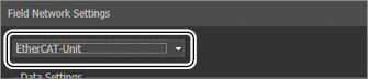
- Change the settings as required.
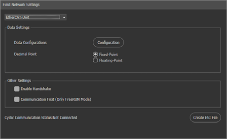
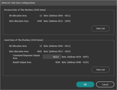
- Click [OK].
Outputting Measurement Data Using EtherCAT Cyclic Communications (Data Output)
Change the output settings for data output using EtherCAT.
Data output flow (example of connection with a PLC EtherCAT unit)
Set the data and address for output in the output settings.
The controller outputs data via EtherCAT in the following manner.
|
|
When used with [Hold Mode] set to [ON], selecting [Update Every Timing] “Field Network” updates the measurement value by inputting TIMING, ZERO, MSR_RESET, and RESET_ALL (the internal measurement value will not update). |
|
|
|
|
|
*1 When the results output handshake is OFF, output data is overwritten and updated without checking whether the Result ack flag is OFF. To take the rise of Result ready flag as a data reference synchronization signal, turn the Result ack flag ON at each output, which will turn the Result ready flag OFF. |
Controlling the Controller with EtherCAT Cyclic Communication (Command Control)
The communication control commands can be executed at any time.
Flow of Command Process using EtherCAT (Example of Connection with the PLC’s EtherCAT Unit)
The controller performs command control via EtherCAT in the following manner.
In the case of a command for which there is no response data, data is not output in response to the Command Data.
|
|
When an error occurs, the command execution results are written to Command Result. (0: Success, <Error code>: Failure). The error cords conform to |
Controlling the Controller with EtherCAT Cyclic Communication (Change Recipe Number)
The recipe number can be changed at any time.
Workflow to change the recipe number
The controller changes the value of the recipe number using EtherCAT as shown below.
The changed value is applied at the next measurement.

Troubleshooting
When correct operation does not occur
To check whether or not the EtherCAT connection is correct
From [Global] for the controller, select [Communications & I/O] - [Field Network], and then check [Cyclic Communication Status:]. If [Not Connected] is displayed here, communication has failed. Check the cable connection and communications settings on the PLC again.
Result OR flag is not output.
The Result OR flag is updated in coordination with results output with EtherCAT as the output destination. When the “Result OR flag” is used, it is necessary to configure the output setting so that one or more data item is output via EtherCAT.
Result ready flag remains ON and does not change.
There is the possibility that “Result ack flag” control is not being performed correctly. The “Result ready flag” turns OFF when the “Result ack flag” rise is recognized in sending (this controller receiving). This is the same regardless of whether “Enable Handshake” is selected or cleared.
Data cannot be acquired correctly when reading data based on the change in the rise of STO output from an external terminal.
STO is the data strobe signal for terminal output. Therefore it cannot be used as the strobe signal for any other data output.
Refer to the “Result ready flag” for the timing as to when to read data by EtherCAT.
Error messages
|
Message |
Cause |
Corrective Action |
Error cause No. |
|
EtherCAT communication has failed. |
Communication was interrupted. (When recovery is possible, recovery occurs automatically.) |
|
13801 |
|
EtherCAT output failed due to a full buffer. |
The controller output buffer for outputting via EtherCAT is full. |
Change the update time on the PLC so the data is output via EtherCAT at a faster rate than it builds up. Or, extend the time between triggers. Note: Results data are not written when the buffer is full. |
13802 |
|
The delay of the handshake causes skipping of the EtherCAT communication result output. |
When the EtherCAT handshake is on, a delayed handshake caused results output via EtherCAT to be skipped. |
Change the update time on the PLC so the data from the tool is output via EtherCAT at a faster rate than it builds up. Or, extend the time between triggers. Note: Results data are not written when the buffer is full. |
13803 |
|
EtherCAT unit is not recognized. |
The EtherCAT unit is not recognized and the controller cannot use EtherCAT communication. |
|
13804 |
Control/Data Output via the PLC-Link
Using the PLC-Link with the Ethernet interface enables the following operations:
- Output data via PLC-Link: Enables the controller measurement data to be output directly to the data register (D) within the PLC.
- Controlling the Controller via PLC-Link: Enables the controller to be controlled by reading the command in the PLC data register (D).
|
|
EtherNet/IP, PROFINET, EtherCAT, and PLC-Link cannot be used at the same time. |
Models that Support the PLC Link Connection
The PLCs of which this unit supports for the PLC link connection is as follows:
Preparing the PLC
1. Wiring overview
The PLC is wired to the controller in the following way.

|
|
When the controller is not receiving commands from the PLC or when it is polling, the PLC does not need to be connected to the terminal block (PLC terminal). |
2. Wire connection at PLC link and settings on the PLC side (Ethernet)
Changing the PLC-Link Settings
The settings for controlling data input and output via the PLC link can be changed on the [Field Network] screen under [Communications & I/O] in [Global].
|
|
|
- Select [Global] → [Communications & I/O] → [Field Network].
- Select [PLC Link].
- Change the settings as required.
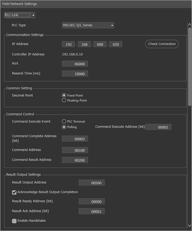
- Click [OK].
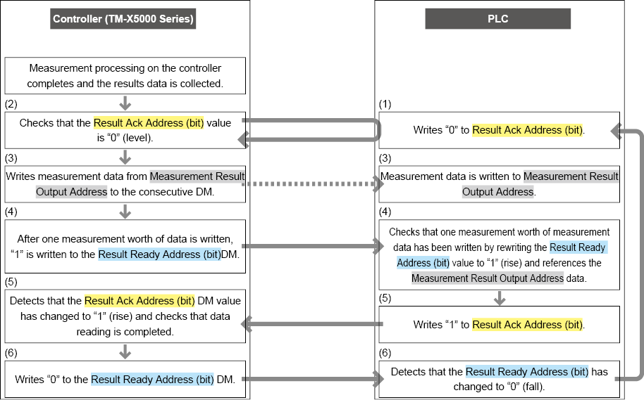
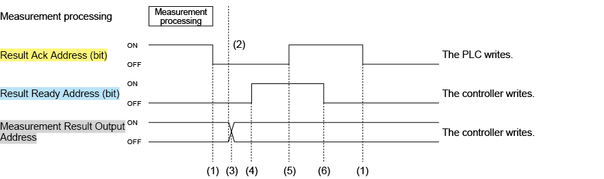
Outputting the Measurement Data with PLC-Link
Data output procedure (Data Output Flow)
This unit outputs data by PLC link with the following procedure.
Set the output items and order for the field network settings in the [Output Settings] results output in advance.
|
|
For processing with the [Acknowledge result output completion] and [Enable Handshake] options enabled, all result data can be retrieved on the PLC side. If not all result data is necessary and it is only needed to retrieve the latest result data on the PLC side, the following settings can reduce the time required to output the results. If [Enable Handshake] is disabled, the Result Ack Address (bit) value confirmation can be restricted in steps 2 and 5 (in this case, the controller outputs the result data regardless of whether data has been completely read or not on the PLC side). Also, if [Acknowledge result output completion] is disabled, writing to Result Ready Address (bit) can be restricted in steps 4 and 6 (in this case, it cannot be determined on the PLC side whether the result data has been updated). |
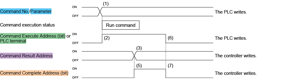
Controlling the Controller via PLC-Link
Set the controller to perform constant monitoring (polling) on the bit changes in the command execute address (bit) or turn the PLC terminal on or off to read and execute a command.
|
|
To execute a command with the PLC terminal method, the PLC terminal must be wired. |
Command execution procedure (Command Processing Flow)
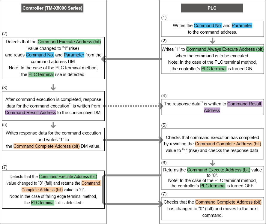
*1 The returned data varies depending on the commands. For details, refer to “List of Communication Commands for Control” and confirm the received data of each command.
Troubleshooting
When correct operation does not occur
When a trigger command is issued by PLC-Link, the capture timing is later compared with trigger signal input from the terminal block.
When a command is executed from PLC-Link, more time is required before execution starts and variation is larger compared with when the terminal block is used (in particular with polling control).
If the timing variation is a problem when capturing an object moving at a high speed, input the trigger from the terminal block.
Data cannot be acquired correctly when reading data based on the change in the rise of STO output from an external terminal.
STO is the data strobe signal for the terminal output unit. Therefore, it cannot be used as the strobe signal for any other data output.
Refer to the result ready address for the timing as to when to read data by PLC-Link.
PLC-Link is established, however, data cannot be written to the connected PLC.
There is a limit to the range of data memory that can be written to. Check the range that can be written to at the connected PLC.
Error messages
|
Message |
Cause |
Corrective Action |
Error cause No. |
|
Failed to establish a link with the PLC. |
An error occurred in the connection with the PLC when the [PLC-Link] function was enabled. |
|
13301 |
|
Unable to output to the PLC-Link due to a full output buffer. |
The controller output buffer for outputting via PLC-Link is full. (When handshake is off) |
Reduce the amount of data to be output so the data is output via PLC-Link at a faster rate than it builds up. Or, extend the time between triggers. Note: Results data are not written when the buffer is full. |
13302 |
|
The delay of the handshake control causes skipping of the PLC communication result output. |
The controller output buffer for outputting via PLC-Link is full. (When handshake is on) |
Reduce the amount of data to be output so the data is output via PLC-Link at a faster rate than it builds up. Or, extend the time between triggers. Note: When the output buffer is full, measurement waits until the buffer is emptied. |
13303 |
Input/Output and Control Using the I/O Terminal
Functions available with the I/O terminal on the controller
The controller has the following ports that act as an I/O terminal:
- Parallel I/O interface: Uses a specialized parallel connection cable (3 m) OP-51657 (sold separately).
- Terminal block interface (OUT/IN): Detachable terminal block included with the controller.
Main functions available with the I/O terminal
Terminal Block Interface (OUT)
Standard specifications
Terminal block (OUT) specifications for the TM-X5000 Series are as follows.
|
|
Tightening above the specified torque may cause damage to the terminal block. |

OUTPUT connector
- Suitable wiring
AWG 16 to 28
- Terminal block screw torque
0.25 N·m or less
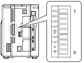
Terminal Layout
|
No. |
Terminal name |
Terminal block display at time of shipment |
Signal |
Signal Description *2 |
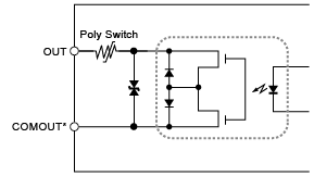
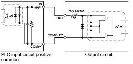
Circuit diagram |
|
1 |
OUT22 |
OUT22 |
RUN *1 |
Run mode output *1 |
A |
|
2 |
OUT23 |
OUT23 |
BUSY *1 |
In-process output *1 |
A |
|
3 |
F_OUT2 |
F_OUT2 |
OR |
Total status output |
A |
|
4 |
F_OUT3 |
F_OUT3 |
STO *1 |
Synchronous signal for output *1 |
A |
|
5 |
COMOUT1 |
COM OUT |
- |
Common for terminal block outputs |
- |
|
6 |
F_OUT0 |
F_OUT0 |
READY *1 |
Trigger input permission output *1 |
A |
|
7 |
F_OUT1 |
F_OUT1 |
ERROR *1 |
Error output *1 |
A |
|
8 |
N.C. |
NC |
- |
- |
- |
|
9 |
COMOUT_F |
COM F |
- |
Common for F_OUT terminal |
- |
|
*1 It is the default assigned value on the terminal where the signal assignment can be changed. These assignments may vary if the Global settings have been changed.
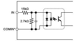
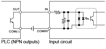
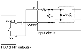
*2
For details on the signal description, refer to
|
|||||
|
|
|
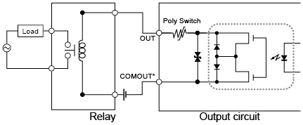
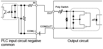
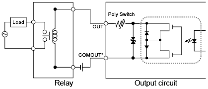
Standard specifications
Terminal block (IN) specifications for the TM-X5000 Series are as follows.
|
|
Tightening above the specified torque may cause damage to the terminal block. |
INPUT connector
- Suitable wiring
AWG 16 to 28
- Terminal block screw torque
0.25 N·m or less
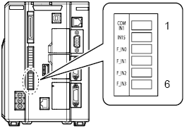
Terminal Layout
|
No. |
Terminal name |
Terminal block display at time of shipment |
Signal |
Signal Description *2 |
Circuit diagram |
|
1 |
COMIN1 |
COM IN1 |
- |
Common for terminal block inputs |
- |
|
2 |
IN15 |
IN15 |
ZERO_ON *1 |
Auto zero ON input *1 |
C |
|
3 |
F_IN0 |
F_IN0 |
TRG *1 |
Trigger input *1 |
B |
|
4 |
F_IN1 |
F_IN1 |
EXT *1 |
Trigger acceptance cancel input *1 |
B |
|
5 |
F_IN2 |
F_IN2 |
TIMING *1 |
Timing input *1 |
B |
|
6 |
F_IN3 |
F_IN3 |
MSR_RESET *1 |
Measured value reset process *1 |
B |
|
*1 It is the default assigned value on the terminal where the signal assignment can be changed. These assignments may vary if the Global settings have been changed.
*2
For details on the signal description, refer to
|
|||||
|
|
|

Parallel I/O Interface
Standard specifications
Parallel I/O Interface specifications for the TM-X5000 Series are as follows.

Terminal Layout
|
No. |
Terminal name |
Signal |
Signal Description |
Circuit diagram |
Cable color |
|
1 |
COMIN2 |
- |
Connector input common terminal |
- |
Brown |
|
2 |
IN0 |
CMD_PARAM0 |
Command parameter bit 0 |
C |
Red |
|
3 |
IN1 |
CMD_PARAM1 |
Command parameter bit 1 |
C |
Orange |
|
4 |
IN2 |
CMD_PARAM2 |
Command parameter bit 2 |
C |
Yellow |
|
5 |
IN3 |
CMD_PARAM3 |
Command Parameter bit 3 |
C |
Green |
|
6 |
IN4 |
CMD_PARAM4 |
Command parameter bit 4 |
C |
Blue |
|
7 |
IN5 |
CMD_PARAM5 |
Command parameter bit 5 |
C |
Purple |
|
8 |
IN6 |
CMD_PARAM6 |
Command parameter bit 6 |
C |
Gray |
|
9 |
IN7 |
CMD_PARAM7 |
Command parameter bit 7 |
C |
White |
|
10 |
IN8 |
CMD_CODE0 |
Command input bit 0 |
C |
Black |
|
11 |
IN9 |
CMD_CODE1 |
Command input bit 1 |
C |
Brown |
|
12 |
IN10 |
CMD_CODE2 |
Command input bit 2 |
C |
Red |
|
13 |
IN11 |
CMD_CODE3 |
Command input bit 3 |
C |
Orange |
|
14 |
IN12 |
CST |
Command confirmation input |
C |
Yellow |
|
15 |
IN13 |
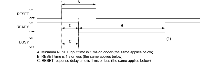
RESET *1 |
Reset input *1 |
C |
Green |
|
16 |
IN14 |
ZERO_OFF *1 |
Auto zero OFF input *1 |
C |
Blue |
|
17 |
COMOUT2 |
- |
Common for connector output terminal |
- |
Purple |
|
18 |
OUT0 |
ACK |
Verification of successfully executed command input |
A |
Gray |
|
19 |
OUT1 |
NACK |
Verification of unsuccessfully executed command input |
A |
White |
|
20 |
OUT2 |
CMD_READY |
Command input permission |
A |
Black |
|
21 |
OUT3 |
MSR_VALID *1 |
Measured value valid output *1 |
A |
Brown |
|
22 |
OUT4 |
- *1 |
(Unallocated) *1 |
A |
Red |
|
23 |
OUT5 |
- *1 |
(Unallocated) *1 |
A |
Orange |
|
24 |
OUT6 |
OUT_DATA0 |
Data output bit 0 |
A |
Yellow |
|
25 |
OUT7 |
OUT_DATA1 |
Data output bit 1 |
A |
Green |
|
26 |
OUT8 |
OUT_DATA2 |
Data output bit 2 |
A |
Blue |
|
27 |
OUT9 |
OUT_DATA3 |
Data output bit 3 |
A |
Purple |
|
28 |
OUT10 |
OUT_DATA4 |
Data output bit 4 |
A |
Gray |
|
29 |
OUT11 |
OUT_DATA5 |
Data output bit 5 |
A |
White |
|
30 |
OUT12 |
OUT_DATA6 |
Data output bit 6 |
A |
Black |
|
31 |
OUT13 |
OUT_DATA7 |
Data output bit 7 |
A |
Brown |
|
32 |
OUT14 |
OUT_DATA8 |
Data output bit 8 |
A |
Red |
|
33 |
OUT15 |
OUT_DATA9 |
Data output bit 9 |
A |
Orange |
|
34 |
OUT16 |
OUT_DATA10 |
Data output bit 10 |
A |
Yellow |
|
35 |
OUT17 |
OUT_DATA11 |
Data output bit 11 |
A |
Green |
|
36 |
OUT18 |
OUT_DATA12 |
Data output bit 12 |
A |
Blue |
|
37 |
OUT19 |
OUT_DATA13 |
Data output bit 13 |
A |
Purple |
|
38 |
OUT20 |
OUT_DATA14 |
Data output bit 14 |
A |
Gray |
|
39 |
OUT21 |
OUT_DATA15 |
Data output bit 15 |
A |
White |
|
40 |
COMOUT2 |
- |
Common for connector output terminal |
- |
Black |
*1 It is the default assigned value on the terminal where the signal assignment can be changed. These assignments may vary if the Global settings have been changed.
Using command inputs via I/O terminals
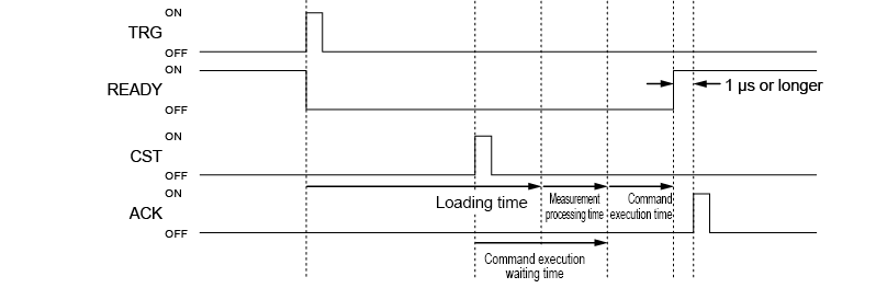
Command input timing
|
|
Command input via the I/O terminal is only available in Run mode. |

I/O command inputs available on the controller
The I/O command inputs available on the controller series are shown below.
|
Value |
Command name |
Command detail |
CMD_CODE (IN8 to IN11) |
CMD_PARAM (IN0 to IN7) |
||||||||||
|
3 |
2 |
1 |
0 |
7 |
6 |
5 |
4 |
3 |
2 |
1 |
0 |
|||
|
0 |
Save Program |
The same function as the SS command (Detail). |
0 |
0 |
0 |
0 |
None |
|||||||
|
1 |
Specify parameter in upper 8 bits |
Used to change the existing Program to above No. 256. |
0 |
0 |
0 |
1 |
0 to 255 |
|||||||
|
2 |
Change inspection program (SD Card 1) |
The same function as PW command (Detail) (fixed to SD1) |
0 |
0 |
1 |
0 |
Program number |
|||||||
|
3 |
Change inspection program (SD Card 2) |
The same function as PW command (Detail) (fixed to SD2) |
0 |
0 |
1 |
1 |
Program number |
|||||||
|
7 |
Write recipe No. |
The same function as the EXW command (Detail). |
0 |
1 |
1 |
1 |
1 to 8: Recipe No. |
|||||||
|
8 |
Clear error |
The same function as the CE command (Detail). |
1 |
0 |
0 |
0 |
None |
|||||||
|
9 |
Change Output File/Folder |
The same function as the OW command (Detail). |
1 |
0 |
0 |
1 |
IN0: Changes data output files when set to 1 IN1: Changes image output folders when set to 1 IN2: Changes simple monitor image output folders when set to 1 |
|||||||
|
12 |
Timing |
The same function as the TIM command (Detail). |
1 |
1 |
0 |
0 |
None |
|||||||
|
13 |
Auto zero |
The same function as the ZR command (Detail). |
1 |
1 |
0 |
1 |
IN0: Requests auto zero OFF when set to 0 and requests auto zero ON when set to 1 |
|||||||
|
14 |
Reset measured value |
The same function as the MRS command (Detail). |
1 |
1 |
1 |
0 |
None |
|||||||
|
15 |
Reset measured value (All templates) |
The same function as the RSA command (Detail). |
1 |
1 |
1 |
1 |
None |
|||||||
1: ON (short), 0: OFF (open)
|
|
|
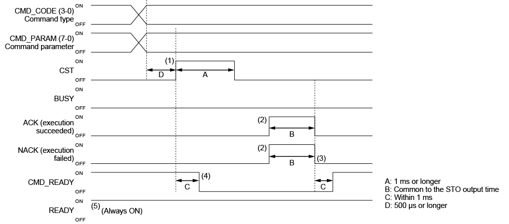
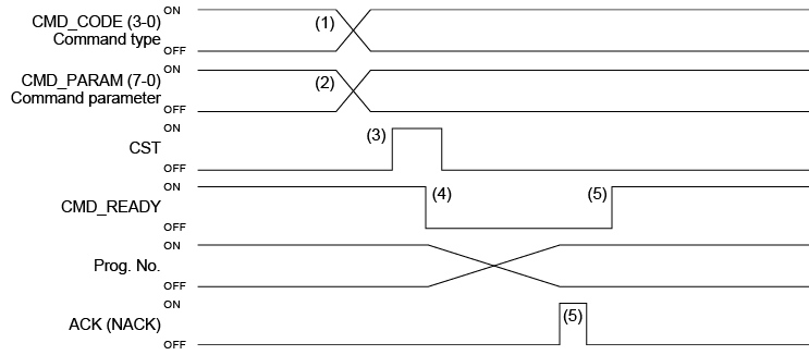
I/O command control procedures
Use the following procedures to operate the controller via the I/O commands.
Example of changing to the program 15 on the SD card 1 using the I/O commands.
|
(1) |
Enter the command codes of the change program (SD card 1) command in CMD_CODE0 to 3. CMD_CODE3: 0 (OFF) CMD_CODE2: 0 (OFF) CMD_CODE1: 1 (ON) CMD_CODE0: 0 (OFF) |
|
(2) |
Enter the codes of program 15 to which the setting is changed in CMD_PARAM7 to 0. CMD_PARAM7: 0 (OFF) CMD_PARAM6: 0 (OFF) CMD_PARAM5: 0 (OFF) CMD_PARAM4: 0 (OFF) CMD_PARAM3: 1 (ON) CMD_PARAM2: 1 (ON) CMD_PARAM1: 1 (ON) CMD_PARAM0: 1 (ON) |
|
(3) |
Turn the input of CST on. |
|
(4) |
CMD_READY turns off and program change starts. |
|
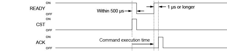
(5) |
When the setting is changed to program 15, ACK turns on for a certain time, and then CMD_READY turns on after ACK falls. |
|
|
ACK output and NACK output duration time is the same as the time set with STO (default: 10ms). |
Outputting judgment values via I/O terminals
Output order
The data specified in the output settings is output from OUT_DATA0 to 15.
The items and order for output can be specified in “Terminal” of [Output Settings].
|
|
|
Example of output
If the output settings are as shown below in a mode other than hold mode, the timing chart is as follows.
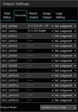
On the output device, read OUT_DATA0 to 15 in synchronization with the leading edge of STO.
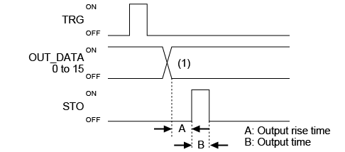
|
(1) |
|
|
OUT6 |
[Outer diameter] judged value |
|
OUT7 |
[Circle diameter] judged value |
|
OUT8 |
[Logic1] judged value |
|
OUT9 |
0 |
|
OUT10 |
0 |
|
OUT11 |
0 |
|
OUT12 |
0 |
|
OUT13 |
0 |
|
OUT14 |
0 |
|
OUT15 |
0 |
|
OUT16 |
0 |
|
OUT17 |
0 |
|
OUT18 |
0 |
|
OUT19 |
0 |
|
OUT20 |
0 |
|
OUT21 |
0 |
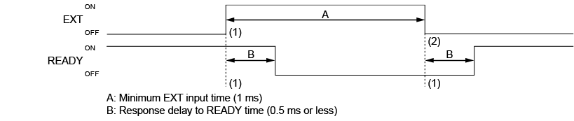
For details on how to set A and B in the diagram above, refer to “External Terminal” (Page 4-4).
If the duration of output cycle via the I/O is longer than the trigger input cycle, priority is given to measurement processing. Therefore, output delay may be caused, which will lead to the data being omitted. To avoid this, set the output cycle time (A + B time) shorter than the trigger input cycle time.
Timing chart
This section describes at what timing the terminal operates with detailed examples.
Standard operation at startup
|
|
|
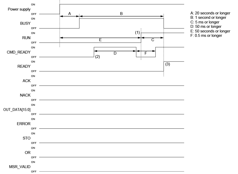
(1) When the system enters [Run] mode, the RUN terminal turns on (when the [Startup mode] is [RUN MODE]).
(2) The CMD_READY terminal turns ON and then OFF after startup. After that when it turns ON, command inputs will be accepted.
(3) When READY is ON, trigger input is possible (when [Trigger mode] is [External]).
Standard operation at trigger input
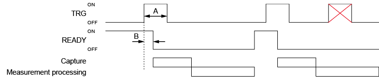
 : As measurement processing has not completed (READY is OFF), the trigger cannot be accepted.
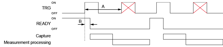
Image Buffer
If [Image Buffer] is ON and the image buffer is empty, READY turns ON and the next trigger can be input even if measurement is being processed.
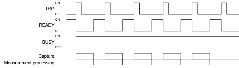
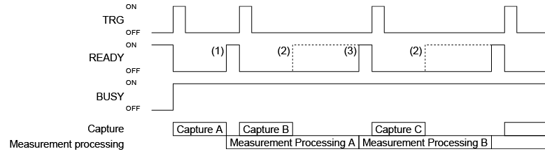
Measurement control (Hold mode)
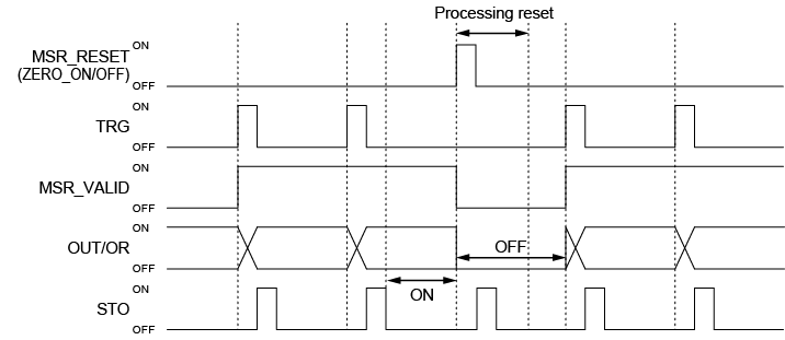
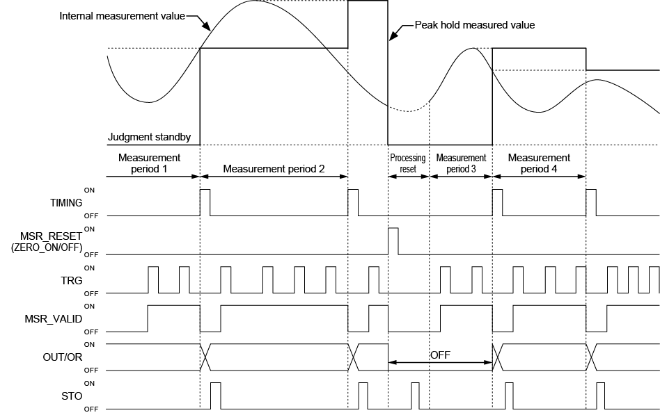
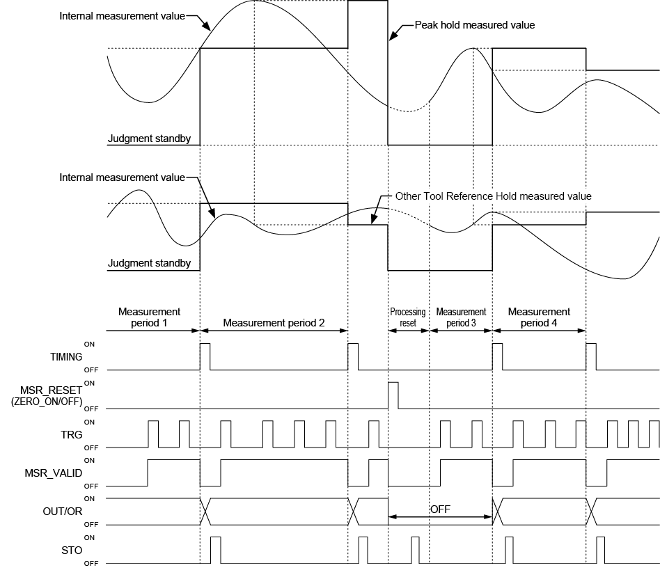
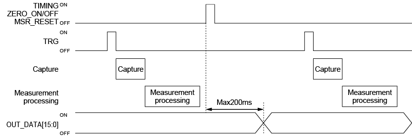
Results output terminal

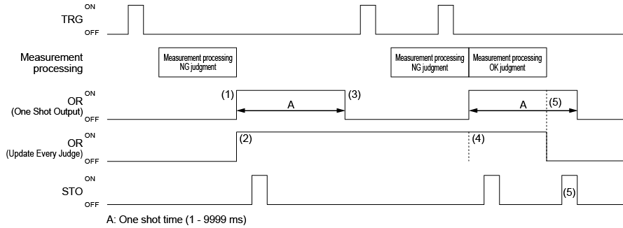
Other control terminals