Read me
Introduction
Read this manual before using the product in order to achieve maximum performance.
Keep this manual in a safe place after reading it so that it can be used at any time.
Symbols
The following symbols are alerts to important messages.
Be sure to read these messages carefully.
|
|
Indicates a hazardous situation which, if not avoided, will result in death or serious injury. |

|
|
Indicates a hazardous situation which, if not avoided, could result in death or serious injury. |

|
|
Indicates a hazardous situation which, if not avoided, could result in minor or moderate injury. |

|
|
Indicates a situation which, if not avoided, could result in product damage as well as property damage. |

|
|
Indicates cautions and limitations that must be followed during operation. |

|
|
Indicates additional information on proper operation. |

|
|
Indicates tips for better understanding or useful information. |

|
|
Indicates the reference pages and items in this manual. |

Precautions
(1) Unauthorized reproduction of this manual in whole or part is prohibited.
(2) The contents of this manual may be changed for improvements without prior notice.
(3) An utmost effort has been made to ensure the contents of this manual are as complete as possible. If there are any mistakes or questions, please contact a KEYENCE office listed in the back of the manual.
(4) Regardless of item (3), KEYENCE will not be liable for any effect resulting from the use of this unit.
(5) Any manuals with missing pages or other paging faults will be replaced.
(6) The screens in this manual are examples for the explanations. The numbers and other values may differ to the actual state of the device.
(7) This manual is created using Windows 10.
(8) This manual describes procedures in most cases with the presumption that the controller is connected to the dedicated display. However, Chapter 7 describes procedures with the presumption that the controller is connected to the TM-X Navigator.
Trademarks
- SD Memory Card is a registered trademark of the SD Association.
- EtherCAT® is a patented technology and registered trademark licensed by Beckhoff Automation GmbH of Germany.
- Other company names and product names noted in this document are registered trademarks or trademarks of their respective companies. The ™ mark and ® mark have been omitted in this manual.
Software information
This product incorporates the software files developed independently by or for Keyence Corporation, software files owned and licensed by a third party, and software files subject to certain open source license agreements.
- The open source software files are subject to the notices and additional terms and conditions. For information about such open source software files, please refer to the “License” information in the “System information” menu under “Global”.
- Such open source software files are provided on an “AS IS” basis to the maximum extent permitted by applicable law.
- If there is any discrepancy between the terms and conditions of the applicable open source license agreement and the “License”, the terms and conditions of the applicable open source license agreement prevail with respect to the applicable open source software.
- A copy may be obtained of the source code corresponding to the binaries for GPL/LGPL-licensed file by sending a request to Keyence customer service at “soft-license@keyence.co.jp”. There will be a charge to cover the costs of providing the source code.
Safety Information for TM-X5000 Series
General Cautions
|
|
|
|
|
|
|
|
|
|
|
|
Precautions for use
|
|
|
|
|
|
Measures to be taken when an abnormality occurs
|
|
Turn the power off immediately in the following cases. Using the unit in an abnormal condition could cause fire, electric shock, or accident. Contact a local KEYENCE office for repair.
|
Operating environment and conditions (precautions on installation/transportation)
|
|
To use the unit properly and safely, avoid installing this unit in the following locations. Failure to do so may cause fire, electric shock or malfunction.
|
|
|
When installing or transporting the TM-X5120, hold both handles to prevent injuries or damage due to the head falling.
|
|
|
|
Maintenance
|
|
|
Caution on wiring
|
|
Some of the I/O circuits of the controller are common internal terminals. Exercise caution to avoid a potential difference between the common internal terminals due to the wiring or potential difference between the external devices. There is a risk of fire occurring. |
Insulated condition between each I/O circuit
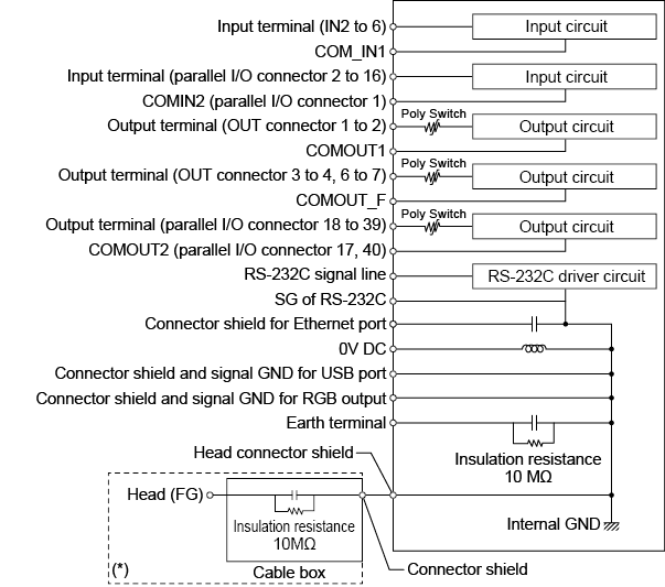
0V DC, Connector shield and signal GND for USB port, Connector shield and signal GND for RGB output, and Head connector shield are all common via a choke coil. Ensure that no potential difference occurs with the PC, PLC, etc. If a potential difference occurs, insulate the power supply of the controller (TM-X5000) from the external device side.
* The cable box of the TM-X5120 is built into the head.
Cautions to take in an positive ground environment
When using TM-X Navigator with a PC connected via USB in a positive ground environment, ensure that the USB terminal is not grounded via the external device. Make sure that the connectors (metallic part) of repeaters and cables, which are between the cable box and the controller, are not grounded.
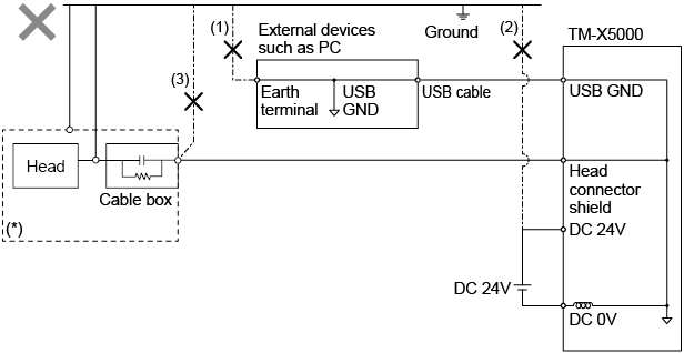
External devices such as a PC (1), the power supply of TM-X5000 (2), or the head connector shield (3) should be insulated from the positive ground terminal.
* The cable box of the TM-X5120 is built into the head.
For Optimal Performance of the TM-X5000 Series
Influence of ambient temperature
A change in the ambient temperature may cause the measurement to fluctuate. Be sure to keep it stabilized.
When the ambient temperature changes by 10 °C, it takes 60 minutes for the distribution of internal temperature to equalize.
Warming up
Wait approximately 30 minutes after the power is turned on before using the TM-X5000 Series. Otherwise, the measured value may gradually fluctuate because the circuit is not immediately stable after the power is turned on.
Operating ambient light intensity level
Do not operate this device near lighting fixtures. If the unit must be used in such a location, install a light shielding board or similar device so that the light will not affect the measurement.
Influence of dust or dirt
The measurement may fluctuate due to dirt, dust, or fluid such as water or oil in the following cases:
- Adhesion on the protective glass plate:
Blow the dirt off with clean air. If dirt persists, wipe the glass surface gently using a soft cloth moistened with alcohol.
- Adhesion on the surface of the measuring target:
Blow the dirt off with clean air or wipe it off.
- Intrusion of floating or sprinkled dust or dirt into the light-axis range:
In this case, take corrective action with a protective cover or air purge.
Influence of vibration
When the measuring target is vibrating, the measured value may fluctuate.
In this case, increase the number of moving averages to achieve a more accurate value.
Measuring target
The measured value may fluctuate if the shapes or surfaces of the measuring targets vary.
In this case, use a target with known dimensions to perform appropriate correction using the scaling function.
Effect of atmospheric motions
Slow atmospheric motions may affect the measurement and result in fluctuation of the measured value.
In such a case, take the following countermeasures.
- Enclose the measurement area with an appropriate enclosure.
- Agitate the air between the measurement point and the workpiece more strongly with a fan.
Precautions on Regulations and Standards
CE and UKCA Marking (Controller/Head)
KEYENCE Corporation has confirmed that this product complies with the essential requirements of the applicable EU Directive(s) and UK regulations, based on the following specifications.
Be sure to consider the following specifications when using this product in the Member States of European Union and in the United Kingdom.
EMC Directive (CE) and Electromagnetic Compatibility Regulations (UKCA)
- Applicable standard : (BS) EN61326-1, Class A
- This product is designed for use in industrial environments.
- All of the cables used to connect the controller and external device should not exceed 30 m.
- Be sure to connect the ground terminal to a grounding.
Remarks:
These specifications do not give any guarantee that an end-product with this product incorporated complies with the essential requirements of EMC Directive and Electromagnetic Compatibility Regulations.
The manufacturer of the end-product is solely responsible for the compliance on the end-product itself according to EMC Directive and Electromagnetic Compatibility Regulations.
CE and UKCA Marking (Hardware Key)
KEYENCE Corporation has confirmed that this product complies with the essential requirements of the applicable EU Directive(s) and UK regulations, based on the following specifications.
Be sure to consider the following specifications when using this product in the Member States of European Union and in the United Kingdom.
EMC Directive (CE) and Electromagnetic Compatibility Regulations (UKCA)
- Applicable Standard
EMI : (BS) EN55032 :2015
EMS : (BS) EN55035 :2017
Remarks:
These specifications do not give any guarantee that an end-product with this product incorporated complies with the essential requirements of EMC Directive and Electromagnetic Compatibility Regulations.
The manufacturer of the end-product is solely responsible for the compliance on the end-product itself according to EMC Directive and Electromagnetic Compatibility Regulations.
CSA Certificate
This product complies with the following CSA and UL standards and has been certified by CSA.
- Applicable Standard
CAN/CSA C22.2 No.61010-1
UL61010-1
Be sure to consider the following specifications when using this product as a product certified by CSA.
- Use the power supply below.
CSA/UL Listing certified power supply with Class 2 output specified by CEC (Canadian Electrical Code) and NEC (National Electrical Code)
- Overvoltage category I
- Use this product under pollution degree 3.
- Use this product at the altitude of 2000 m or less.
- Mount the head on a metallic plate.
- Indoor use only.
North American Regulations
This product complies with the following North American regulations.
- Applicable regulation
FCC Part15 Subpart B, Class A Digital Device
ICES-003, Class A Digital Apparatus
- Operation is subject to the following two conditions: (1)This device may not cause harmful interface, and (2) this device must accept any interference received, including interference that may cause undesired operation.
Note:
This equipment has been tested and found to comply with the limits for a Class A digital device, pursuant to part 15 of the FCC Rules. These limits are designed to provide reasonable protection against harmful interference when the equipment is operated in a commercial environment. This equipment generates, uses, and can radiate radio frequency energy and, if not installed and used in accordance with the instruction manual, may cause harmful interference to radio communications. Operation of this equipment in a residential area is likely to cause harmful interference in which case the user will be required to correct the interference at his own expense.
- FCC CAUTION
Changes or modifications not expressly approved by the party responsible for compliance could void the user’s authority to operate the equipment.
Best Management Practice for Perchlorate Materials - California only
This product uses components containing perchlorate material. When shipping this product or installing end-product containing this product to California, you must label or mark the following statement on the exterior of all outer shipping packages and on consumer packages or you must include the following statement in an instruction manual or MSDS accompanied with the product.
|
“Perchlorate Material – special handling may apply, See www.dtsc.ca.gov/hazardouswaste/perchlorate.” |
KC mark (Republic of Korea) (for Dedicated monitor for TM-X only)
|
사 용 자 안 내 문 |
|
이 기기는 업무용 환경에서 사용할 목적으로 적합성평가를 받은 기기로서 가정용 환경에서 사용하 는 경우 전파간섭의 우려가 있습니다. |
Safety Precautions on LED product
The degree of risk of this product is shown below.
|
Light source |
Risk Group * |
|
InGaN Green LED |
Exempt Group |
* LED product is classified as shown below according to IEC 62471.
|
Does not pose any photobiological hazard. |
|
Does not pose a hazard due to normal behavioral limitations on exposure. |
|
Does not pose a hazard due to the aversion response to ver bright light sources or due to thermal discomfort. |
|
May pose a hazard even for momentary or brief exposure. |
Software License Agreement
NOTICE TO USER: PLEASE READ THIS SOFTWARE LICENSE AGREEMENT (“THIS AGREEMENT”) CAREFULLY. BY USING ALL OR ANY PORTION OF THE TM-X Navigator (“THIS SOFTWARE”), YOU ARE AGREEING TO BE BOUND BY ALL THE TERMS AND CONDITONS OF THIS AGREEMENT. IF YOU DO NOT AGREE TO THE TERMS OF THIS AGREEMENT, DO NOT USE THIS SOFTWARE.
If you install, copy and or use all or a portion of this Software on a device or computer, you will be deemed to have agreed to all the terms of this Agreement, and this Agreement will come into effect.
1. Definitions
1.1. “Use” or “using” refers to the accessing, installing, downloading, copying, operating and or otherwise benefiting from the utilization of this Software.
1.2. “This Software” denotes the software and all associated documentation provided by KEYENCE.
1.3. “User” or “User’s” infers the company or persons who have had the license to use this Software granted to them by KEYENCE.
2. Grant of License.
2.1. In compliance with all of the terms and conditions of this Agreement, KEYENCE grants the nonexclusive and non-transferable license to install and use this Software.
2.2. The granting of the license permits the single reproduction and or copying of this Software for the User’s backing up or archiving purposes.
2.3. This Software maybe installed on multiple devices and computers for the User’s benefit and use.
2.4. The transfer of this Software via devices and computers with this Software installed on them by the User to third parties is permitted. In such a case, the third party who receives this Software may continue to use this Software in the same manner as the previous User.
2.5. With the transfer of this Software to a third party, the original User may install this Software to additional devices and computers for further use as required. In such a case, the third party who receives this Software may continue to use this Software in the same manner as the previous User.
2.6. The User maintains and guarantees that any thirdparties (as detailed in the previous two sections) who receive and use this Software agree to this license Agreement and comply with all the terms and conditions.
3. Restrictions.
3.1. This Software may not be modified by the User in any form except from the installation of updates or new functions provided by KEYENCE.
3.2. The reverse engineering, decompiling or disassembling of this Software by any persons are not permitted.
3.3. Without the prior permission of KEYENCE, the User may not reproduce or copy this Software for selling or distributing to a third party.
4. Intellectual Property Rights.
Except as stated herein, KEYENCE reserves all rights, titles and interests in this Software, along with all associated copyrights, trademarks, and other intellectual property rights.
5. Disclaimer.
This Software is licensed to the User “AS IS” and without any warranty of any kind. In no event does KEYENCE or its suppliers accept or assume any liability for any damages, claims, costs or profit loss as a result of operating this Software.
6. Termination.
6.1. Under this Agreement the User’s license will automatically terminate if this Software and any associated copies of this Software are destroyed or voluntarily returned to KEYENCE.
6.2. Under this Agreement the User’s license will terminate immediately and automatically without any notice from KEYENCE if there is any failure to comply with any of the terms and conditions of this Agreement. Upon termination, the using of this Software shall cease, and all copies (full or partial) of this Software should be destroyed or returned to KEYENCE.
6.3. Compensation will be sought by KEYENCE should any violation or breach of this Agreement result in any incurred costs or lost profit to KEYENCE.
7. Governing Law.
7.1. This Agreement will be governed by and construed in accordance with the substantive laws of Japan.
7.2. If any part of this Agreement is found void and unenforceable, the rest of this Agreement will remain intact, valid and enforceable according to the associated terms and conditions.
Changes to each version of the TM-X5000 Series
Major Changes to Ver. 1.1
Additions/changes related to tools
- The following tools were added:
- Element: Gauge line
- Auxiliary: Line through point, approximate line, median circle, approximate circle, figure circle
- Application: Gap
- The [List Editor] function was added to enable tolerance and other settings to be edited all at once (Detail).
- Zero reset can now be input by tool from the dedicated monitor for TM-X and TM-X Navigator (Detail).
- The processing time for each tool is now displayed.
- Many tools, such as peak line and center line, can now be selected as the base line for the width of specific position tool (Detail).
- The result of [Region Adjustment at Setting] in the [Specify Region] is now kept (Detail).
- Fitting can now be done on the base line in [Region Adjustment at Setting] in the [Specify Region] (Detail).
- An [Arbitrary Line] and [Arbitrary Point] can now be fitted on an existing line and point respectively (Detail).
Additions/changes related to [Utility]
- Measurement no longer stops when the maximum number of points (20,000) is exceeded with the statistics function (Detail).
- Improved support for CSV output on the dedicated monitor for TM-X, clearing of statistical data accumulated with the clear button, and others (Detail).
- Added a histogram to the statistics function (Detail).
Additions/changes related to [Global] Settings
- Added a security function (Detail).
- Added [Tool Memory Usage] to system information (Detail).
- Added support for Simplified Chinese and German (Detail).
- Added “Decimal Point Notation” to the system language and enabled periods and commas to be selected (Detail).
Additions/changes related to the [Edit] menu
- Added main view numeric display colors and enabled numbers to be displayed in green (when OK) and red (when NG) (Detail).
- An active processing pattern can now be displayed in Run mode (Detail).
- Added support for saving display resolution (low and high resolution) in Run mode (Detail).
Other additions/changes
- Added [PC] (when using TM-X Navigator) to selection for head changeover and image output destination and head selection when saving with the archived image function (Detail).
- The screen can now be captured on any screen by right-clicking (Detail).
- Omitted images (1/X omissions) can now be used in the following ways:
Main Changes to Ver. 1.2
Additions/changes related to head settings
- Added “Trigger Multiple Times” to the external trigger (Detail).
- 25 µs, 50 µs, and 100 µs can now be selected for the exposure time (Detail).
- In addition to average image, the image array operations of dark and bright composition were added to create “Image Composition” (Detail).
|
|
The above functions can be used with the controller of Ver.1.2.**** and the head of Ver.1.0.0101. The head can be upgraded by upgrading the controller to which the head is connected. |
Additions/changes related to tools
- The type of image (standard image/head image/archived image) that is being displayed on the main screen of the measurement settings screen in [Setup] mode can be changed. (Detail).
- Added maximum and minimum widths to the external radius tool (Detail).
- [None (absolute value)], [Forward], and [Reverse] can now be selected for [+/- Direction] in the measurement value for the LN - LN, LN - PT, PT - PT, CL - CL, CL - LN, and CL - PT tools(Detail).
- Up to four position correction groups can now be set in one processing pattern (Detail).
- The elements for the position correction and measurement tools and measurement time can now be checked on a list (Detail).
- [Batch Test] can now be run for archived images in setup mode (Detail).
- Added [Nearest Hold] and [Other Tool Reference Hold] to hold mode (Detail).
- [Inscribed] and [Circumscribed] can now be selected for circle diameter, circle, approximate circle, and combined circle (Detail).
- Added the [Batch LN - PT] tool to the application tools (Detail).
- Added [Circle] to the pattern region of a pattern search (Detail).
- Added [Select List] when selecting an element tool from the measurement tools (Detail).
- Elements can now be re-selected when editing measurement tools (Detail).
Additions/changes related to [Utility]
- Added [EtherCAT Memory Monitor] in accordance with support for EtherCAT (Detail).
- [Archived Image Settings] can now be configured from utilities (Detail).
- [Head-to-head Adjustment Execution] and [Head-to-head Adjustment Setting] were added to measure a large object with two heads (Detail).
Additions/changes related to [Global] Settings
- The minute and second of arc can now be selected for the angle display unit (Detail).
- EtherNet/IP, PROFINET, and EtherCAT units are now supported (Detail).
- Added support for Korean and Thai (Detail).
- Added [Communication Expansion Unit] to [Connection Devices] under [System Information] in accordance with adding support for the communication expansion unit (Detail).
Additions/changes related to the [Edit] menu
Added support for [Multiple Copy] and [Inverted Copy] as functions when copying tools (Detail).
Other additions/changes
- Changed the save format for capture image to JPEG.
- Images can now be displayed in high resolution during a trial run.
- The statistical analysis trend graph can now be enlarged vertically and horizontally.
- Added support for [Automatic Connection] when connecting from the dedicated monitor for TM-X (TM-MP120) or TM-X Navigator to the controller (Detail).
Main Changes to Ver. 1.3
Additions/changes related to tools
- The following tools were added:
- Element : Pitch element (circle/arc distance), Pitch element (straight line angle), Contour extraction, OBD element (Over Ball Diameter)
- Application : Master difference (contour), Ring thickness, Thread
- Geometrical tolerance : Contour profile
- The angle and distance from the reference can now be specified in [Region Adjustment at Setting] in [Specify Region] (Detail).
- The center line/center of the circle for position correction can now be specified as a reference in [Region Adjustment at Setting] in [Specify Region] (Detail).
- Black width ratio can now be specified with [Gauge Width] in the gauge line tool (Detail).
- A line, point, circle, chamfer, and corner arc can now be specified as a reference tool (Detail).
- Tool position correction can now be changed with the list editor (Detail).
Additions/changes related to [Global] Settings
Added support for Chinese (Traditional), French, Italian, Mexican Spanish, Czech, Hungarian, and Polish (Detail).
Additions/changes related to the [Edit] menu
- The LN - LN tool can now be replaced with the diameter tool (Detail).
- The software now supports the copying of recipes (Detail)/(Detail).
Other additions/changes
- The software now supports the CAD import function (Detail).
- The software now supports BMP image output in simple monitor output (Detail).
Main Changes to Ver. 1.4
Additions/changes related to head settings
- Added “Mask Region” to optical axis alignment (Detail).
Additions/changes related to tools
- Added [Profile Intersection] and [Tool Reference (Point)] to auxiliary tool.
- Changed [Pitch Count] to [Count].
- In [Width of Specific Position], the same line can now be set as the basis for multiple positions consecutively (Detail).
- In [Calculation], [Standard] and [Advanced] can now be selected (Detail). In [Advanced], [Variables], [Measured Value], [Measurement Information], [Judgment Result] and [Position Correction Result] now can be referred to.
- In [Gap], the processing mode (Stable/Fast) can now be selected (Detail).
- In [OBD Element], circle in the chamfer can now be set as a range (Detail).
- The display color of “Element” and “Auxiliary” tool can now be changed (Detail).
- In the [Master Difference (Area)], process to include the black frame that is in the non-measurement range in the measurement range can now be selected (Detail).
Additions/changes related to [Utility]
- The data used in the statistics can now be selected from [Start loading past data] or [Start from the latest data] (Detail).
- In [Head-to-head Adjustment Execution], the positions between heads can now be manually adjusted (Detail).
Additions/changes related to commands.
The following commands were added:
- ICCW: write image composition capture cycle (Detail)
- ICCR: read image composition capture cycle (Detail)
- TSW: write tool settings (Detail)
- TSR: read tool settings (Detail)
- TSC: clear tool settings (Detail)
- OASR: obtain optical axis state (Detail)
Additions/changes related to the [Edit] menu
- [Delete All Unreferenced Tools] is now available (Detail).
- The imaging files can now be saved (Detail).
- The settings of [Excel Transfer Setting] can now be saved (Detail).
Other additions/changes
- On the setup screen of [Position Correction], [Image Display] is now available.
- In [Output Settings] → [Image Output] → [Detailed Settings], JPG can now be selected for [File Format] (Detail).
- For the thumbnail images displayed in [Archived Image] and [Batch Test], the accumulated number of images and their image number are now displayed. In addition, the ID number of the selected image is displayed (Detail).
- TM-X Navigator is now compatible with Windows11 Pro (Detail).
Main Changes to Ver. 1.5
Additions/changes related to the compatible hardware
It is now compatible with TM-X5120.
Additions/changes related to tools
- In [Calculation (Advanced)], the row number is now displayed on the left side of the input field. Additionally, the row number is displayed when a syntax error occurs.
- Added guides to [Advanced Edge Settings].
Additions/changes related to commands.
The following commands were added:
- S0: switch to setup mode(Detail)
- R0: switch to run mode(Detail)
- STW: replace the externally specified string(Detail)
- STR: read the externally specified string(Detail)
Other additions/changes
In [Output Settings] → [File Naming Rule], [Custom] is now available(Detail).
Compatibility
Compatibility of controller versions with the dedicated monitor for TM-X (TM-MP120)*
|
Dedicated monitor for TM-X (TM-MP120) |
|||||||
|
Ver.1.0.xxxx |
Ver.1.1.xxxx |
Ver1.2.xxxx |
Ver1.3.xxxx |
Ver1.4.xxxx |
Ver1.5.xxxx |
||
|
Controller |
Ver.1.0.xxxx |
|
|
|
|
|
|
|
Ver.1.1.xxxx |
|
|
|
|
|
|
|
|
Ver1.2.xxxx |
|
|
|
|
|
|
|
|
Ver1.3.xxxx |
|
|
|
|
|
|
|
|
Ver1.4.xxxx |
|
|
|
|
|
|
|
|
Ver1.5.xxxx |
|
|
|
|
|
|
|
|
: Connection possible
|
|||||||

* This is the same as when connecting from the TM-X Navigator to the controller (terminal function).
Compatibility of controller* versions with program files
|
Program File |
|||||||
|
Ver.1.0.xxxx |
Ver.1.1.xxxx |
Ver1.2.xxxx |
Ver1.3.xxxx |
Ver1.4.xxxx |
Ver1.5.xxxx |
||
|
Controller |
Ver.1.0.xxxx |
|
|
|
|
|
|
|
Ver.1.1.xxxx |
|
|
|
|
|
|
|
|
Ver1.2.xxxx |
|
|
|
|
|
|
|
|
Ver1.3.xxxx |
|
|
|
|
|
|
|
|
Ver1.4.xxxx |
|
|
|
|
|
|
|
|
Ver1.5.xxxx |
|
|
|
|
|
|
|
|
: Can be loaded
|
|||||||
* This is the same for the TM-X Navigator simulator.
