Measurement Sensors
Dimension Measurement
Displacement Measurement
Surface Defects That Impair Welding Quality
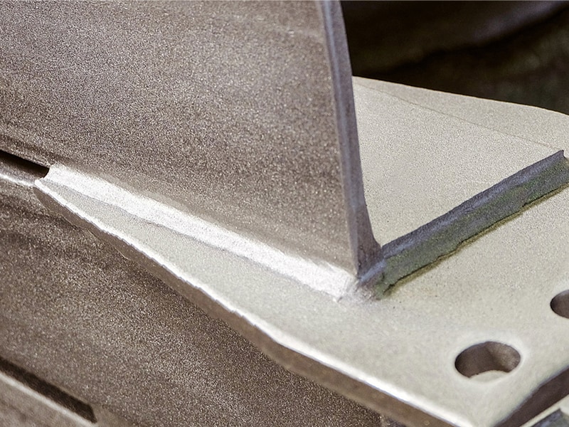
Welding is one of the most important and commonly used fabrication processes for fusing materials (usually metals) together via heat. The process relies on melting the metal and adding filler material, which then cools to form a joint.
However, the process is more complex than it sounds, and failure to maintain good control over it can result in different types of defects.
In principle, welding processes have to join materials in accordance with drawings based on appropriate welding design. In addition, it is essential to ensure welding quality, including weld appearance and strength. This page introduces typical surface defects that impair welding quality.
Understanding Common Welding Surface Defects
To understand how to improve welding quality, it's important to understand what causes weld surface defects. Porosity and cracks inside the welding joints and on their surfaces happen for different reasons, but most are tied to high temperatures that facilitate the joining process.
Porosity happens when small gas pockets or voids become trapped in the cooling molten metal, forming a void inside the weld. That void is often visible on the surface, and its presence indicates a poor welding technique or exceptionally poor quality of the filler material. Cracks, on the other hand, form due to thermal stresses within the material or due to impurities in the material itself.
Spatter is another defect in welding that occurs when molten metal is expelled from the pool during the welding operation. It often happens during electric arc welding, but other welding techniques may also cause a spatter. In most cases, it's easily removable. Slag inclusions, on the other hand, are a real issue.
Slag usually rises to the top of inadequately formed joints. If it doesn't separate itself from the joint once the joint cools down, it's easily removed with a few light taps. However, some impurities don't separate themselves from the joint. Instead, they band together but remain trapped within the welded joint, forming a weak spot that's a shortcut to joint failure.
We’re here to provide you with more details.
Reach out today!

Pits
Pits (open defects) are surface defects produced when gas cavities formed inside the weld metal solidify after the gas escapes from the bead*1 surface. Gas cavities remaining inside the bead are an internal defect known as blow holes. The causes of these defects include the use of improper shielding gas*2; insufficient deoxidizer; oil, rust, plating or other matter adhering to the surface of the groove*3 in the base material; and moisture contained in the material.
*1 The elevation of the joint surface consisting of finished weld.
*2 Gas used to block out atmosphere in order to prevent the oxidization or nitriding of molten metal during welding.
*3 A beveled opening created in a weld joint before welding to achieve necessary penetration.
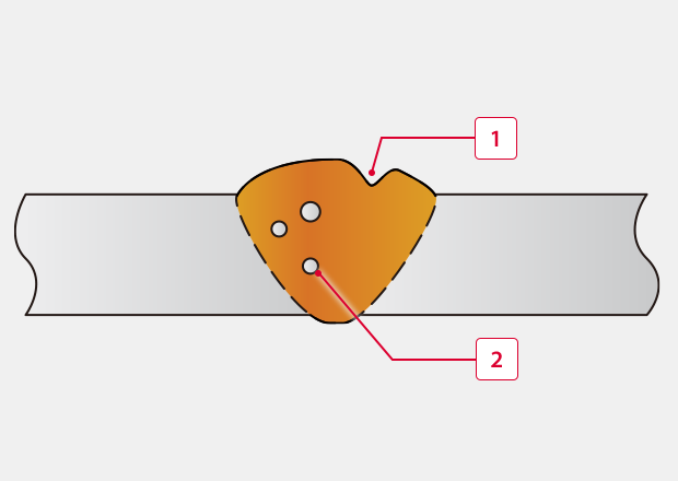
-
1Pits
-
2Blow hole
Undercut
Undercut is a groove at the weld toe produced by the base material*4 exiting weld. Typical causes are excessively high welding current or welding speed. Too much weaving*5 width may also be the cause of undercut.
*4 Material to be welded in a process where a filler material is used. When a filler material is not used, it is called "weld material."
*5 A welding motion typically used for arc welding that moves the torch from side-to-side almost perpendicular to the weld line.This motion can deposit more weld metal with fewer passes.
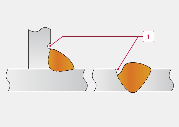
-
1Undercut
Overlap
Overlap occurs when molten metal flows over the surface of the base material and then cools without fusing with the base material. A typical cause of overlap is the supply of too much weld metal due to low welding speed. Overlap in fillet*6 welds is caused by the droop of excessive molten metal due to gravity. The necessary countermeasure is to review the welding conditions (such as setting higher welding speed or lower welding current).
*6 A weld joint with a triangular cross section that joins two surfaces together at approximately 90 degrees.
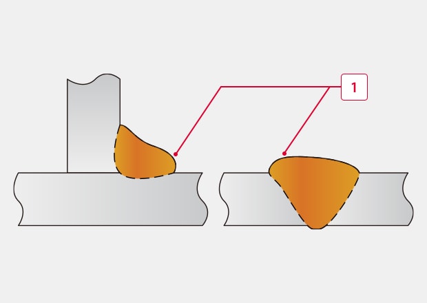
-
1Overlap
Insufficient Reinforcement
Reinforcement is the weld metal built up above the surface in excess of the required dimension in the groove weld or fillet weld. A typical cause is fast welding speed (moving speed of the heat source) that makes the deposition of the weld metal in the groove insufficient.
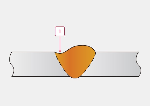
-
1Insufficient reinforcement
Surface Cracking
Surface cracking forms cracks in the surface of hot welds immediately after welding. It is broadly divided into solidification cracking and liquefaction cracking. Solidification cracking occurs when the weld is solidifying. Liquefaction cracking occurs in multi-layer welding when the previous welding layer is melted by subsequent welding. Another classification refers to the generated position and shape of the crack, such as longitudinal cracking, toe cracking, transverse cracking, crater cracking, and so on.
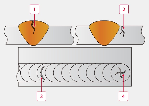
-
1Longitudinal cracking
-
2Toe cracking
-
3Transverse cracking
-
4Crater cracking
Discover more about this product.
Click here to book your demo.

Arc Strike
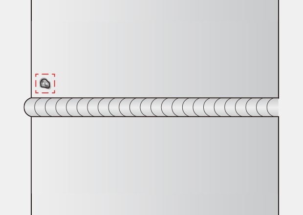
This is a defect caused by instantaneously striking an arc on the base material. In other words, an arc strike is a spot of failed arc ignition which was not fused by subsequent welding and remained on the base material. Arc strike may be the cause of cracking in the base material.
A similar defect may occur when large spatter*7 particles adhere and remain on the surface.
*7 The scattering of slag or metal droplets during welding which typically degrades welding quality.
Bead Meandering (Bent/Misaligned Bead)
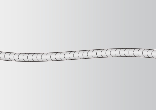
This defect occurs when the bead meanders and deviates from the weld line*8. Possible causes include the wave or curl in the automatically supplied weld wire not being corrected properly or the directions of the weld line and wire curl being at right angles to each other. This defect may also occur when the settings of the wire supply speed and welding current do not match.
*8 A line representing a bead or a weld. A line to be welded, a line being welded or a welded line.
Remaining Groove
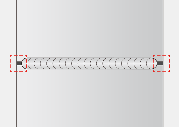
This is a state where parts of the groove are not welded and remain open because the process could not form a bead continuing from the start point to the end point of the groove. When this defect is found in robot welding around the start or end point, there may be a problem in the robot control. If the arc, gas or wire supply is unstable, the groove may also remain open in the middle of the bead.
We’re here to provide you with more details.
Reach out today!

Analyzing Causes of Weld Surface Imperfections
Surface defects occur for several reasons. For one, welding demands the use of proper technique that follows adequate prep work. In most cases, the welded surfaces are often contaminated by oils, rusk, or dirt, all of which have to be removed prior to welding.
Assuming that you have adequate welding equipment, forming a good weld also requires the appropriate welding power setting, the correct electrode size, and the correct angle, speed, and motion associated with the welding technique.
Failure to fulfill any of these requirements often results in poorly formed welding joints and plenty of weld surface imperfections.
Strategies for Preventing Welding Surface Defects
As previously mentioned, proper prep work plays a crucial role in preventing welding surface defects. This includes cleaning metal surfaces thoroughly before the welding itself. Also, selecting the right electrode size, the right welding technique, and the right setting for the specific welding job all reduce the likelihood of defects forming on the surface or within the welded joint.
Techniques to Correct Surface Defects in Welding
In most cases, correction is often done through grinding and re-welding the defective section or the entire joint. This often rectifies surface imperfections like porosity, cracks, and slag inclusions.
Adequate heat treatment of the welded joint relieves internal stresses within the joint. This doesn't alleviate porosity and slag inclusions, but it nearly eliminates the risk of cracks forming during nominal operation.
Evaluating the Impact of Surface Defects on Weld Integrity
Surface defects are a serious problem in the context of welding, and they're not something a bit of sandpaper and duct tape can alleviate. Defects such as porosity and cracks significantly reduce the load-bearing capacity of the weld, while slag inclusions often act as starting points for corrosion.
This underscores the importance of detecting these defects promptly before the welded joints are put under any cycling loading conditions. That's where KEYENCE comes in. As the world's leading provider of precision measurement technologies, our products are often used in manufacturing and quality control, including laser displacement sensors and laser profilers used in weld inspection across numerous industries.
Contact KEYENCE today to see how our technologies can help you detect and prevent surface defects in your welding processes.
Contact us to learn more about how our advanced technology can help take your business to the next level.
Contact Us
Related Downloads

Learn a wide variety of topics about welding technology from welding types and mechanisms to robotic automation of welding. Detailed explanations are also given for the causes and phenomena of welding defects as well as measurement and inspection methods vital to welding quality management.
Related Products
Applications
Dimension Measurement
- Thickness and Width Measurement
- Step Height Measurement
- Inner and Outer Diameter Measurement
- Measuring Angles
- Meandering/Edge Measurement
Displacement Measurement
- Positioning and Stroke Length Measurement
- Vibration and Runout Measurement
- Deflection Measurement
- Measuring Eccentricity

