Measurement Sensors
Electron Beam Welding
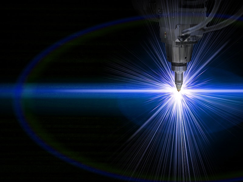
Electron beam welding is accomplished by generating an electron beam in a vacuum and using the resulting heat to weld parts. However, recent advancements have led to the development of machines capable of welding in low-vacuum conditions or with a moving electron gun.
Components of an Electron Beam Welder
An electron beam welder consists of several critical components that work together to generate and control the electron beam used for welding. The components of electron beam welders differ from one model to the other, but all major components remain the same regardless of the electron welding machine model and make.
These major components include:
- Electro gun
- The electron gun accelerates, generates, and focuses the electron beam gained by thermo-emission from a hot metal strap or wire.
- Vacuum camber
- The entire welding process takes place in a vacuum chamber to prevent the electrons from scattering due to air molecules, ensuring that the electron beam remains focused and stable.
- Positioning mechanism
- This consists of a mechanical system that moves the workpiece in precise increments on various axes. This is usually done via computer numerical control (CNC), which ensures highly accurate and repeatable welds.
- Power supply
- Power supplies must be able to output anywhere from 30-200 kV depending on the system.
- Control electronics
- Control electronics monitor and adjust the welding parameters in real time. These parameters include beam current, focus, and deflection, ensuring optimal welding conditions.

Applications of Electron Beam Welding
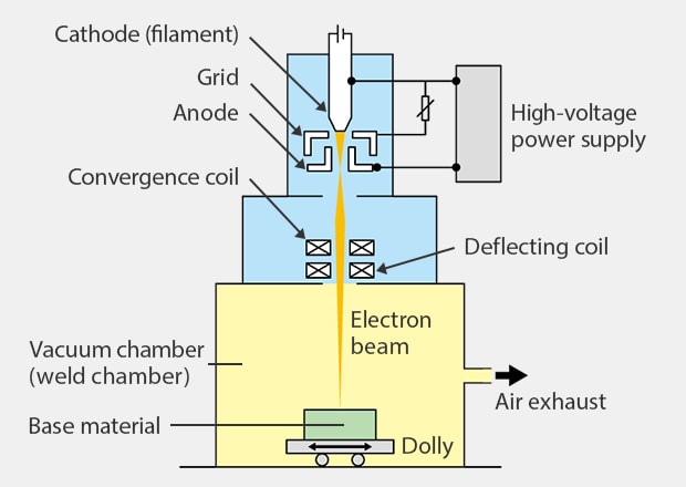
With a beam spot diameter of about 0.2 mm and significantly higher energy density than arc welding, electron beam welding allows for precise control over penetration, making it adaptable to various base materials, including those with high melting points or prone to oxidation. The process relies on the principle of heating a cathode in a vacuum to emit electrons, which are then accelerated, converged, and directed onto the base material to generate high heat energy, facilitating welding. This makes this method applicable to a wide variety of base materials—from thick to thin plates—and even for ultra-detailed welding. Currently, developed electron beam welding techniques do not require a vacuum, opening the door to a growing range of applications, including shipbuilding, bridge construction, aerospace, and electronics. For electronic components, a specialized process known as electron beam sealing is employed to seal components like crystal oscillators in a vacuum, ensuring their integrity.
Benefits of an Electron Beam Welding Machine
Electron beam welding is known for its precision, making it a popular automated welding choice for the aerospace, defense, medical, instrumentation, and automotive industries. As such, it offers a slew of different benefits.
Speed and Efficiency
Compared to more conventional welding techniques, electron beam welding achieves significantly higher welding speeds due to its inherent efficiency. The focused energy of the electron beam allows for rapid heating and melting of the material.
Additionally, this allows deep penetration into the material, often enabling welding sections at 30 mm per second in a single pass. This reduces the need for multiple passes, further increasing the efficiency of the welding process.
Precision and Control
The precisely controlled electron beam can be focused onto a very small spot size, which offers fast and efficient welding without sacrificing precision. This is crucial for industries that demand detailed work on small or complex parts.
Furthermore, operators can precisely adjust the parameters associated with beam control, including beam power and focus. This level of control accommodates different material types and thicknesses, granting a higher degree of control over the entire welding process.
Minimal Heat-Affected Zone (HAZ) and Distortion
As noted, the working principle of electron beam welding relies on a high-energy electron beam focused on a miniscule area. This significantly reduces the heat-affected zone—the zone affected by thermal changes during the welding process—which is very important when dealing with materials sensitive to microstructural changes.
However, the reduced heat-affected zone means the surrounding material remains relatively cool, further minimizing the risk of distortion and warping. This particular characteristic is crucial in applications that demand dimensional accuracy and the integrity of the welded components.
Lastly, the minimized thermal input and reduced heat-affected zone also help maintain the base material’s mechanical and physical properties, which is vital for high-performance welding applications.

Electron Beam vs Laser Welding
Laser welding, another high-precision technique, offers advantages such as not requiring a vacuum, smaller equipment size, and higher welding speeds. However, its lower output limits penetration depth, rendering it less suitable for welding thick plates and materials with highly reflective surfaces.
Laser welding techniques encompass various methods, including heat conduction welding and keyhole (deep penetration) welding. Heat conduction welding, characterized by its low output, is suitable for thin plates and materials sensitive to heat effects. Keyhole welding, utilizing high-output lasers, enables rapid, uniform welds with minimal distortion, making it ideal for deep penetration or welding multiple base materials.
Comparing Electron Beam Welding and Laser Welding
| Electron beam welding | Laser welding | ||
|---|---|---|---|
| CO2 (carbon dioxide) laser | YAG laser | ||
| Heat source device | High-voltage generator + electron gun | Optical resonator with CO2 as the main medium | Optical resonator with a YAG rod as the medium |
| Output range of commercially available equipment | 3 kW to 100 kW | 0.5 kW to 45 kW | 0.1 kW to 6 kW |
| Maximum melting capacity | Approx. 150 mm (100 kW) | Approx. 30 mm (45 kW) | Approx. 10 mm (6 kW) |
| Beam energy efficiency | Approx. 100% | Approx. 20% Significant loss due to surface reflections and plasma absorption |
Slightly higher surface absorption coefficient than CO2 with less plasma absorption |
| Practical maximum plate thickness | Approx. 100 mm | A few mm or less | Same as left |
| Welding atmosphere | Vacuum (<10-2 mm Hg) Welding must be performed in a vacuum |
Ambient air Inert gas shielding required as with arc welding |
Same as left |
| Weld materials | Metals only No metal materials with high vapor pressure such as zinc and magnesium |
Metals, non-metals | Same as left |
Electronic Beam Welding Couplings
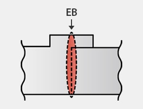
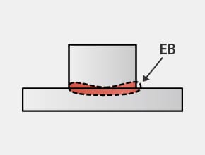
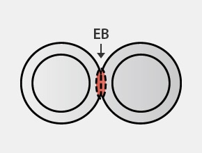
Electron beam welding is known for its ability to create small, focused weld spots with minimal heat impact on base materials. While seamless couplings are preferred, slight gaps up to 0.1 mm are typically acceptable when welding with a maximum penetration depth of 3 to 5 mm. Deeper penetrations afford greater tolerance for larger gaps. For instance, at a depth of 50 mm, even a 3 mm gap can be accommodated through the use of filler material like welding wire.
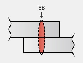
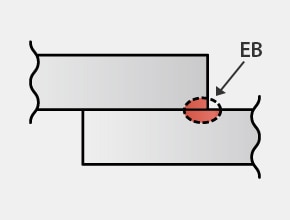
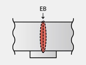
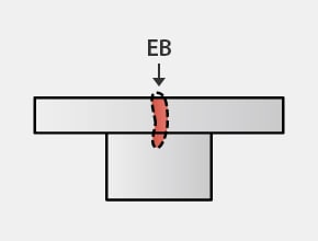
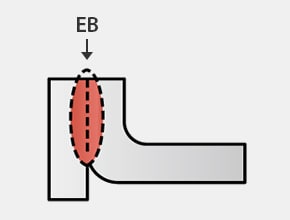
Typical weld couplings possible with electron beam welding (EB = electron beam)
Lap
Lap fillet
Overlapped butt

I-shaped butt
I-shaped butt (with backing)
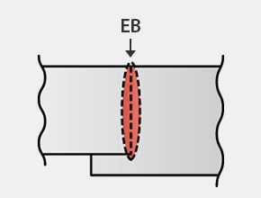
I-shaped butt (stepped)
T-shaped through-hole
T-shaped fillet
Edge
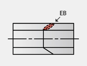
Diagonal butt
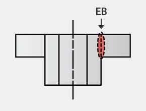
Tube
Pipe cutting line
Remote Welding and Laser Deposit Welding
Remote laser welding further enhances productivity and flexibility via mirrors and quick movements of the welded part. It allows high-speed welding with minimal physical travel, making it ideal for the high-volume production of complex and intricate parts.
Laser deposit welding, also known as laser cladding or direct metal deposition, uses filler materials to form metallurgical bonds between the base material and filler. This process serves purposes ranging from joining to surface repair and component manufacturing. If you’re looking to upgrade your organization’s welding quality inspection process, KEYENCE offers a wide range of laser displacement sensors and laser profilers with exceptional accuracy. Contact us today to learn more.

Related Downloads


Related Products
Applications
Dimension Measurement
- Thickness and Width Measurement
- Step Height Measurement
- Inner and Outer Diameter Measurement
- Measuring Angles
- Meandering/Edge Measurement
Displacement Measurement
- Positioning and Stroke Length Measurement
- Vibration and Runout Measurement
- Deflection Measurement
- Measuring Eccentricity
