Machining Centers
- 1. Major Functions and Characteristics
- 2. Emergence and Development of Machining Centers
- 3. General Structure and Types of Machining Centers
- 4. Differences Between Horizontal and Vertical Types
1. Major Functions and Characteristics
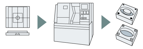
Today, machining centers are widely used in manufacturing sites. Machining centers are critical equipment for machining metal parts and components in addition to their primary purpose of die manufacture. As an example, machining centers in the automobile industry are used for efficient grinding and drilling of engine parts as well as for making dies for body components. Many other products commonly used in daily life and in industrial settings are manufactured in machining centers.
Machining centers feature a computerized automatic tool change function. In general, an operator must exchange the tools on an NC machine tool. Machining centers, however, have a change arm that automatically retrieves and exchanges tools from a tool magazine where the tools are stored during the machining of workpieces. This saves time and effort required for standard tool changeovers, and consequentially enables automated and power-saving operations while reducing costs.
In recent years, the emergence of five-axis machining centers, equipped with two rotational axes in addition to the conventional three axes, has enabled machining of shapes with even greater complexity.

2. Emergence and Development of Machining Centers
Manufacturing metal parts generally includes grinding surfaces and grooves in addition to using a number of complex machining methods such as drilling, boring (enlarging holes), and threading. Conventionally, different cutting tools such as mills, end mills, drills, boring tools, and taps were selectively used for these machining processes.
With the emergence of NC lathes later on, a manually-operated tool change function called a turret was developed, making blade exchanging more convenient. Machining centers take this idea one step forward through computer-controlled automated tool exchanges. Machining centers can continuously perform several types of machining at the same time on different surfaces of a workpiece, greatly improving production efficiency. Even today machining centers are still improving with advances in machining precision and speed year after year, making them a fundamental part of the manufacturing process.
Visit any metalworking factory to see a number of machining centers working ceaselessly day in and day out. Only a few on-site operators are required to monitor the machines.
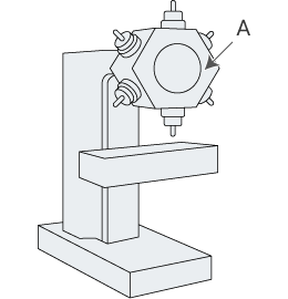
With NC lathes, tools are attached to a turret, which is turned manually.
- A
- Turret
3. General Structure and Types of Machining Centers
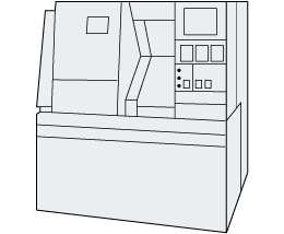
Machining centers can be broadly classified into three types based on their structure: horizontal, vertical, and gantry types. The horizontal type—the first to be developed—can be defined simply as a machine where the spindle to which the cutting tool is attached is mounted horizontally (or parallel to the floor). In contrast, vertical types have the spindle set upright. Gantry types, on the other hand, have a gate-like structure with the spindle mounted on the ceiling of the gate, facing downward.
Using the horizontal type as an example, the general structure of a machining center consists of a base part called a bed at the bottom, a saddle that moves on the bed, a table attached on top of the saddle for placing the raw material, a column installed perpendicularly to the bed, and a spindle head where the cutting tools are attached.
4. Differences Between Horizontal and Vertical Types
Horizontal machining centers have a blade-mounted spindle that comes out sideways, which machines workpieces in the horizontal direction. The column moves along the X axis, the saddle along the Y axis, and table along the Z axis, and this combination enables three-dimensional machining. Additionally, some models have a B axis that rotates the table horizontally, making it possible to machine materials using a total of four axes.
One advantage of horizontal types is the capability to machine four surfaces of a workpiece―when using a four-axis machining center with B axis―all at once. This eliminates the need for operators to manually switch the four sides of the workpiece, and thus also contributes to higher machining precision. Moreover, machining from the horizontal direction allows chips to fall down, which helps prevent the chips from accumulating on the workpiece and digging into the blade.
Conversely, vertical machining centers have the spindle in a vertical position, and workpieces are machined from above. Generally, the table travels horizontally on the X and Y axes, and the spindle moves vertically, enabling triaxial machining.
Compared with horizontal types where the spindle is situated to the side of the workpiece, vertical types take up less installation space, making them a popular choice. In addition, machining from above the workpiece allows operators to work while comparing the machining to the design drawings. However, machining on the top of the workpiece causes chips to accumulate on the workpiece, creating the need for a blower that uses compressed air, or rinsing with lubricant to remove the chips appropriately.
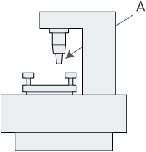
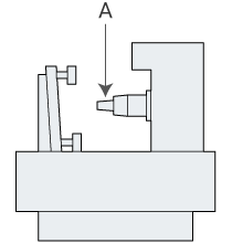
- A
- Spindle with tool attached


