Data Acquisition (DAQ)
Basics of Resistance Thermometers
This section introduces the basics of resistance thermometers, how to select them, and key points in using them.
What Are Resistance Thermometers?
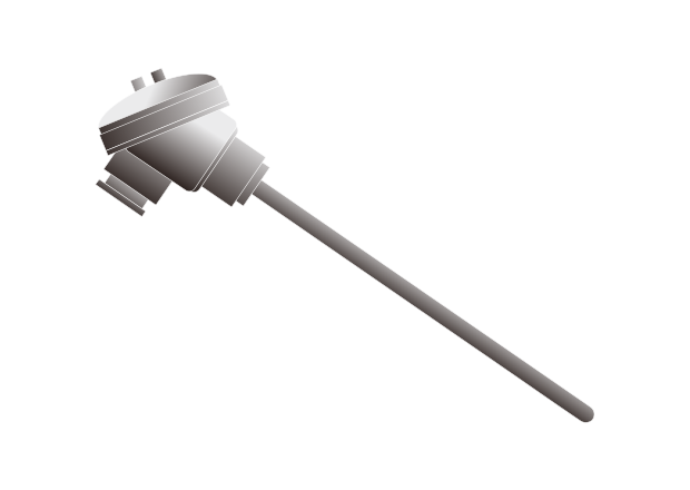
Resistance thermometers are sensors that measure the temperature by utilizing the characteristics of a metal or metal oxide in which its electrical resistivity varies with temperature change and by measuring that resistivity.
These thermometers are also called RTDs (resistance temperature detectors).
As a metal used in resistance thermometers, platinum (Pt100) is generally employed due to its stable characteristics and easy availability.
The use of this metal ensures compatibility between each manufacturer.
At present, resistance thermometers, together with thermocouples, are the most commonly used temperature sensors.
Characteristics of Resistance Thermometers
Resistance thermometers are used to measure the temperature accurately.
- Capable of measuring the temperature accurately
- Capable of measuring very low temperatures
The two greatest advantages of resistance thermometers are those listed above. On the other hand, these sensors are not suited for high-temperature measurement.
In general, resistance thermometers are used for measuring environmental temperatures, whereas thermocouples are selected for measuring industrial furnace temperatures.
Principle of Resistance Thermometers
The resistance value of the resistive element of a resistance thermometer changes at a fixed ratio with temperature changes.
The temperature is derived by passing a certain current through the resistive element, measuring the voltage at both ends of it with an instrument, and calculating the resistance value through Ohm’s Law (E = IR).
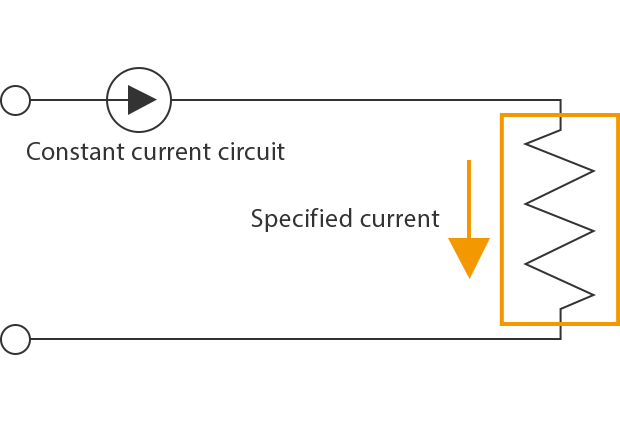
The resistance value of this element varies with the temperature.
Because the specified current is constant,a change in the resistance value also changes the voltage on both ends of the resistor.
The temperature is measured using this change in the voltage.
Reference: Reference Temperature Conversion Table for Pt100
| Temperature (°C) | -100 | 0 | Temperature (°C) | 0 | 100 | 200 | 300 | 400 | 500 | 600 | 700 | 800 |
|---|---|---|---|---|---|---|---|---|---|---|---|---|
| 0 | 60.26 | 100 | 0 | 100 | 138.51 | 175.86 | 212.05 | 247.09 | 280.98 | 313.71 | 345.28 | 375.7 |
| -10 | 56.19 | 96.09 | 10 | 103.9 | 142.29 | 179.53 | 215.61 | 250.53 | 284.3 | 316.92 | 348.38 | 378.68 |
| -20 | 52.11 | 92.16 | 20 | 107.79 | 146.07 | 183.19 | 219.15 | 253.96 | 287.62 | 320.12 | 351.46 | 381.65 |
| -30 | 48 | 88.22 | 30 | 111.67 | 149.83 | 186.84 | 222.68 | 257.38 | 290.92 | 323.3 | 354.53 | 384.6 |
| -40 | 43.88 | 84.27 | 40 | 115.54 | 153.58 | 190.47 | 226.21 | 260.78 | 294.21 | 326.48 | 357.59 | 387.55 |
| -50 | 39.72 | 80.31 | 50 | 119.4 | 157.33 | 194.1 | 229.72 | 264.18 | 297.49 | 329.64 | 360.64 | 390.48 |
| -60 | 35.54 | 76.33 | 60 | 123.24 | 161.05 | 197.71 | 233.21 | 267.56 | 300.75 | 332.79 | 363.67 | |
| -70 | 31.34 | 72.33 | 70 | 127.08 | 164.77 | 201.31 | 236.7 | 270.93 | 304.01 | 335.93 | 366.7 | |
| -80 | 27.1 | 68.33 | 80 | 130.9 | 168.48 | 204.9 | 240.18 | 274.29 | 307.25 | 339.06 | 369.71 | |
| -90 | 22.83 | 64.3 | 90 | 134.71 | 172.17 | 208.48 | 243.64 | 277.64 | 310.49 | 342.18 | 372.71 | |
| -100 | 18.52 | 60.26 | 100 | 138.51 | 175.86 | 212.05 | 247.09 | 280.98 | 313.71 | 345.28 | 375.7 |
unit: Ω

How to Select Resistance Thermometers
Selection Based on Resistive Elements
Resistance thermometers are generally classified into the following four types.
| Type | Measurement Range |
|---|---|
|
Type
Platinum resistance thermometers
|
Measurement Range
-200 to +660°C (-328 to +1220°F)
|
|
Type
Copper resistance thermometers
|
Measurement Range
0 to +180°C (32 to +356°F)
|
|
Type
Nickel resistance thermometers
|
Measurement Range
-50 to +300°C (-58°F to +572°F)
|
|
Type
Platinum-cobalt resistance thermometers
|
Measurement Range
-272 to +27°C (-457.6 to +80.6°F)
|
The characteristics of each type of resistance thermometer are listed below.
Platinum Resistance Thermometers
These resistance thermometers are most widely used for industrial measurement due to their large change in resistance values with temperature and due to their high stability and accuracy.
Platinum resistance thermometers are classified into the two major types listed below. Pt100 is the most commonly used.
| Symbol | Resistance at 0°C (32°F) | Resistance ratio |
|---|---|---|
|
Symbol
Pt100
|
Resistance at 0°C (32°F)
100 Ω
|
Resistance ratio
1.3851
|
|
Symbol
Pt10
|
Resistance at 0°C (32°F)
10 Ω
|
Resistance ratio
1.3851
|
Resistance ratio: Resistance at 100°C (212°F) / Resistance at 0°C (32°F)
Copper Resistance Thermometers
These resistance thermometers have a small variation in temperature characteristics and are inexpensive. However, their size cannot be reduced due to their small resistivity (specific resistance).
Also, as they are easily oxidized at high temperatures, the upper operating temperature is limited to approximately +180°C (+356°F).
Nickel Resistance Thermometers
These resistance thermometers have a large change in resistance values per 1°C (1.8°F) and are inexpensive.
However, they have a low upper operating temperature limit because of, for example, their transformation point around +300°C (+572°F).
Platinum-Cobalt Resistance Thermometers
These are sensors that use platinum/cobalt dilute alloy for their resistive elements and are used for measuring very low temperatures.
Selection Based on the Accuracy
The accuracy of resistance thermometers is specified as the “tolerance for measured temperatures.”
| Class | Tolerance (°C) |
|---|---|
|
Class
A
|
Tolerance (°C)
±(0.15 + 0.002│t│)
|
|
Class
B
|
Tolerance (°C)
±(0.3 + 0.005│t│)
|
│t│: Absolute value of measured temperature
Selection Based on How Internal Conductors Are Wired
Internal conductors are wired in a two-, three-, or four-wire system.
Two-Wire System

A wiring system in which one conductor is connected to each end of the resistive element.
Although this system is inexpensive, it is necessary to check and adjust the resistance of the conductor beforehand because the conductor resistance is added as it is the resistance value. As such, this is not a practical system.
Three-Wire System

This is the most commonly used wiring system, in which two conductors are connected to one end of the resistive element and one conductor to the other end.
Its feature is that you can avoid the effect of the conductor resistance if the three conductors have the same length, material, wire diameter, and electric resistance.
Four-Wire System

A wiring system in which two conductors are connected to each end of the resistive element.
The measurement principle is such that although this system is expensive, you can use it to completely avoid the effect of the conductor resistance.
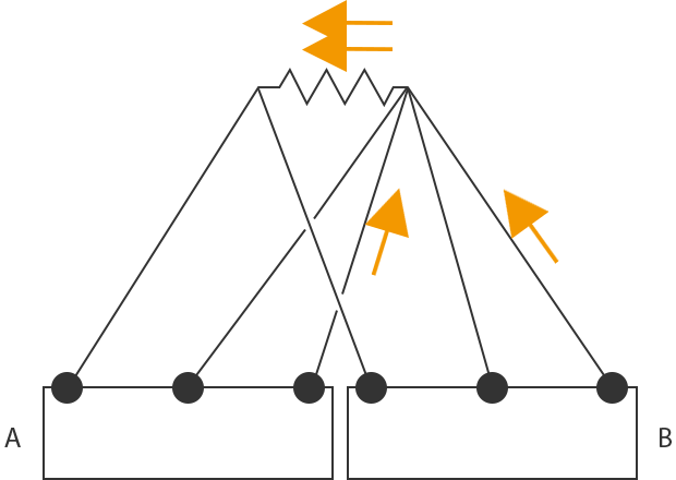
Why is a Three-Wire Resistance Thermometer Not Affected by the Conductor Resistance?
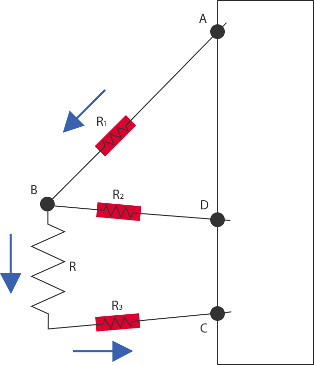
As shown in the figure, a three-wire resistance thermometer is configured with two conductors connected to one end of the resistive element and one conductor to the other end.
With the resistance of the resistive element as R and the resistance of the three conductors as R1, R2, and R3, respectively (R1 = R2 = R3), the specified current flows in the path from A to B to C.
(It does not flow to R2 because B and D have the same potential)
At this time, the recorder to which a three-wire resistance thermometer is wired measures the voltage between A and B and the voltage between B and C and records their difference as the measured value.
Because the value of the flowing current is constant, the voltage that passes through each resistor as
R: V
R1, R3: V1
(Voltage between B and C) − (Voltage between A and B)
= (V + V1) − (V1)
= V
In this way, the effect of the conductor resistance can be avoided.
Selection Based on the Structure
General Resistance Thermometers (Equipped With Protection Tubes)
This is the most basic structure of a resistance thermometer in which internal conductors are connected to the resistive element, the conductors and the element are contained in a protection tube, and a terminal is attached to the structure to enable the use of the resistance thermometer.
You can select a protection tube that has high vibration and corrosion resistance. Major advantages are low prices and easy handling.
On the other hand, this structure has the disadvantage of slow responsiveness due to it being larger than the sheath resistance thermometers described below.
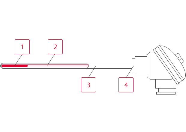
-
1Resistive element
-
2Internal conductors
-
3Protection tube
-
4Terminal
Sheath Resistance Thermometers
These resistance thermometers are structured by integrating internal conductors and a resistive element into a metallic sheath and filling the sheath with highly pure MgO (magnesium oxide).
Their biggest advantage is quick responsiveness thanks to their thin tube with no air layer in it.
As with other advantages, you can also freely bend the shape and reduce the outer diameter.
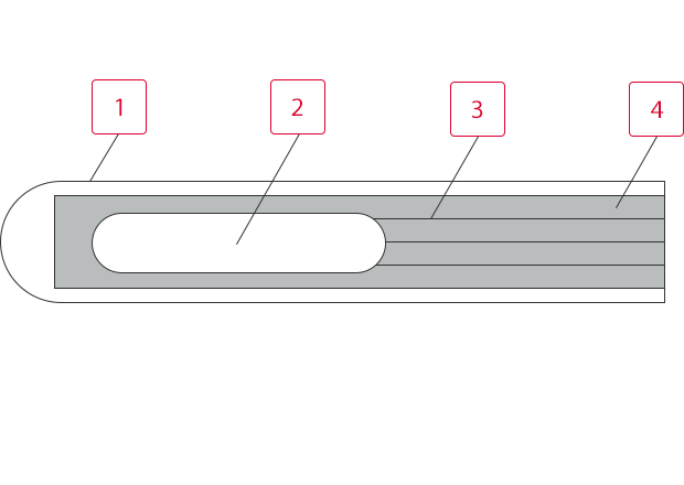
-
1Metallic sheath
-
2Resistive element
-
3Internal conductors
-
4MgO (magnesium oxide)
What is a “Double Element”?
The resistive element of a resistance thermometer is sometimes simply called an “element.”
Generally, only one resistive element exists in a resistance thermometer, a structure that is called a “single element.”
“Double-element” refers to a type of resistance thermometer in which two resistive elements exist. This type is used for the following purposes.
- To improve the reliability against failure, such as disconnection of internal conductors.
- To display and record the same measured values on multiple instruments (such as recorders and temperature regulators).

Key Points in Using Resistance Thermometers
Caution Regarding Errors Caused by Internal Conductors
A resistance thermometer calculates the temperature by accurately measuring the resistance value of the internal resistive element. As such, it is necessary to minimize the effect of the conductor resistance as much as possible. In the case of the three-wire system or the four-wire system, make sure that the conductors have the same material, outer diameter, length, and electric resistance and that there is no temperature gradient.
Is It Possible to Extend a Resistance Thermometer?
Yes, by using a conductor for a resistance thermometer.
If you need a long conductor, check the resistance value per meter of the conductor so as not to generate errors. Select a conductor within the input signal source resistance range for your recorder.
Caution Regarding Errors Caused by Insertion Depth
An accurate temperature cannot be measured unless the temperature measuring section of the resistance thermometer is installed to have the same temperature as that of the measurement target.
Irrespective of the resistance thermometer type (the type equipped with a protection tube or the sheath type), be sure to insert a length of the temperature measuring section that is approximately 15 to 20 times the outer diameter.
Caution Regarding Errors Caused by Self-Heating
When measuring the temperature using a resistance thermometer, the specified current is passed through the thermometer to obtain the temperature. At this time, Joule heat is generated, which heats the resistance thermometer itself.
This is called “self-heating.”
Self-heating is proportional to the square of the specified current (it also depends on the resistance thermometer structure and the environment), and errors in accuracy may be caused if this heating is large.
In general, the accuracy of a resistance thermometer is guaranteed according to the applicable specified current, so you do not have to worry about self-heating as long as you use the specified current described in the specifications.
Caution Regarding the Specified Current of a Resistance Thermometer
The specified current of a resistance thermometer is defined in the specifications.
Do not pass a current other than the specified one described in the specifications.
Doing so may lead to the following problems.
- Changes in the quantity of heat generated cause measurement errors.
- Change from the specified current also changes measured voltage values, causing incorrect temperatures to be displayed.
Caution Regarding Parallel Wiring
Use a double-element type resistance thermometer when wiring one resistance thermometer in parallel with multiple recorders.
If you use a single-element type, be sure to prepare one resistance thermometer for each recorder.
What is the Problem With Parallel Wiring? (Single-Element Type)
A recorder passes the specified current through a resistance thermometer and measures the voltage generated at both ends of the resistor.
Parallel wiring causes the specified current to be supplied from two recorders, thereby offering inaccurate measured voltages.
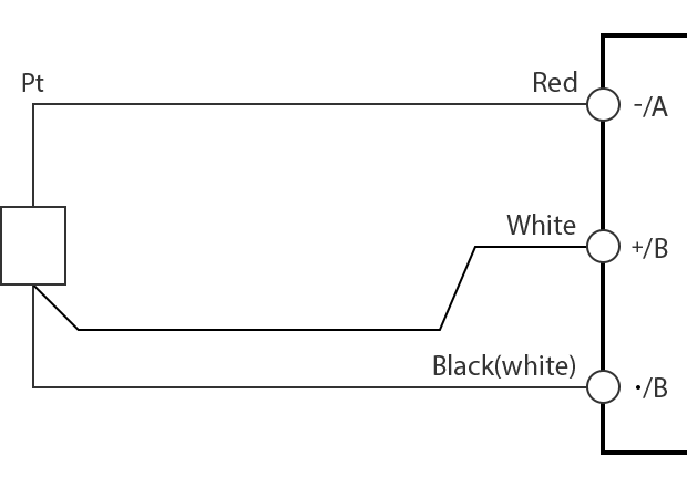
Caution Regarding the Wiring Position of Conductors Attached to the Recorder
Wire conductors properly to the recorder. Failing to do so will result in incorrect temperatures being displayed.
The following figure shows how to wire a three-wire resistance thermometer to a recorder.
Because this wiring uses the resistance thermometer as a three-wire type, the accuracy corresponds to that of a three-wire type.
Reference 1

How to wire a two-wire resistance thermometer to a recorder designed to measure a three-wire resistance thermometer.
Reference 2

How to wire a four-wire resistance thermometer to a recorder designed to measure a three-wire resistance thermometer.
How Accurate is a Resistance Thermometer?
Resistance thermometers, also known as RTDs, are incredibly accurate temperature measurement devices, and their high stability and accuracy make them perfect for conducting measurements in the industrial setting, where reliability and repeatability are paramount.
Platinum resistance thermometers are the most accurate and stable type of resistance temperature detectors because they’re constructed using high-purity platinum elements. They’re so accurate and reliable that they’re used for interpolating temperature under the International Temperature Scale of 1990.
As such, they’re categorized into accuracy classes AA, A, and B, according to the standard IEC 60751. Class AA resistance thermometers typically have the lowest error margin—in other words, they’re the most accurate. However, it’s important to note that the accuracy of a resistance thermometer is often defined at a specific calibration point, usually at 0°C.
This means that, besides depending on the tolerance of the base resistance, the accuracy also might vary with the temperature. Class AA resistance thermometers are accurate up to ±0.01°C, while class A has around ±0.15°C accuracy, while Class B might be accurate up to ±0.3°.
For example, if you’re using a Class AA resistance thermometer to measure an object that’s heated up to 400°C, the thermometer might offset measurement results in the range of 399.99°C and 400.01°C.
What Are the Advantages of Resistance Thermometers?
Resistance thermometers, especially PT ones, offer a host of benefits that make them popular for accurate temperature measurements. Their accuracy and precision make them a reliable choice for industrial process applications with critical temperature readings, and their stability in high temperatures over prolonged periods ensures that the readings remain consistent over time—which is great for long-term monitoring.
The repeatability of their measurements is an additional bonus, as resistance thermometers are capable of producing consistent results under identical conditions, which is invaluable for processes that rely on repeatability. Furthermore, their relatively linear relationship between temperature and electrical resistance eliminates the need for complex conversations, thus simplifying the interpretation of readings. In fact, by just measuring the resistance and knowing the temperature range, one can easily calculate temperature by employing Ohm’s Law.
Lastly, resistance thermometers are designed to withstand the rigors of industrial environments—more specifically, they’re designed to be less prone to electrical interference, which many other devices and sensors might struggle with.
What is the Difference Between a Thermistor and a Resistance Thermometer?
While both devices are used to sense and measure temperature, a thermistor and a resistance thermometer differ primarily in their materials and how well or fast they respond to temperature fluctuations. A thermistor is a resistor made of polymer or ceramic material whose resistance drastically changes with temperature.
Due to their non-linear, exponential temperature response, they’re quite sensitive to even the slightest temperature fluctuations, which is useful for applications that rely on highly sensitive temperature measurements.
Resistance thermometers, on the other hand, are often made of materials such as platinum, which changes resistance with the temperature in a linear and quite predictable manner. This makes them highly accurate and stable over a wide temperature range, which is ideal for industrial applications that require precise and consistent measurements.
Given how they’re used in a variety of industrial settings, thanks to their accuracy, wide temperature range, and reliability, resistance thermistors are highly standardized and accuracy-rated devices.
![Temperature Measurement Basics [Resistance Thermometers]](/img/asset/AS_118847_L.jpg)