- Home
- Solutions
- Case Studies
- Taking Defect Analysis of Materials to a Whole New Level
Taking Defect Analysis of Materials to a Whole New Level
Quality control specialists working within the manufacturing environment, or experts in research and development (R&D) working on product prototypes, need to have a complete picture of any defects that exist in the materials they work with. This is the case whether components are metal, plastic or a composite.
One of the biggest issues they face is that while these defects can be miniscule, and certainly invisible to the naked eye, they can occur on a regular basis and have a significant impact on production quality and efficiency – and indeed on a company's bottom line.
Many of those tasked with checking for defects in materials are hampered by having to rely on relatively basic microscopes or some type of hand-held measurement instrument like Vernier calipers or a micrometer. This sort of equipment is traditionally used to measure larger manufacturing errors once discovered, but the tiniest defects are, by their very nature, far more difficult to spot. To make matters worse, with most microscopes the operator is looking top-down on to a sample, which makes it very difficult to determine whether the problem is a dent, a scratch or a raised section. Being restricted to working in a two-dimensional (2D) plane increases the likelihood of spending large amounts of time checking for material defects, but still not getting the most representative results.
Another issue for inspectors is that the vast majority of microscopes used in defect analysis on materials provide low magnification observation and are unable to store an image in sufficiently high resolution to prevent blurring or pixelation when zooming in. This prevents grain structure in metals from being seen clearly for accurate analysis and makes it difficult to check grain size or carry out particle analysis of the structure when working with composites.
R&D departments and quality control departments in manufacturing settings have also struggled with carrying out detailed analysis on parts that are too large for checking with a standard microscope. Inspecting paint finishes on car doors, for example, can be both a problematic and challenging process.
Finally, working with analog microscopes makes it impossible to share in real-time any data gathered during defect analysis with colleagues or departments on other sites or in other parts of the world. Generating paper reports can be time consuming and they often won't contain the level of detail that's required for in-depth analysis.
The solution
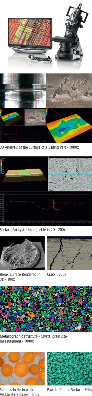
The answer to these numerous issues is to use a digital method of defect analysis in materials that makes it easy to produce detailed reports that can be shared near-instantaneously around the world. Digital inspection also provides readings in 4K resolution which means crystal clear images whatever the level of magnification.Enter the VHX-7000 from KEYENCE, the world’s first 4K ultra-high accuracy microscope. It offers magnifications from 20x to 6000x and has the ability to subtly shift the finely-tuned XY motorised stage automatically to increase resolution by 33%. An optical shadow effect mode enhances uneven surfaces still further and enables subtle contours to stand out.
Such a powerful digital microscope not only handles most problems associated with material defect analysis but also identifies issues that quality control specialists didn't even know they had. It does this by enabling them to check materials to a level of detail that simply wasn't available before. With most standard microscopes, many defects in materials can slip through inspection; unsurprisingly, users of the VHX-7000 will often find faults that were previously undetectable, such as bubbles, contamination, burrs, corrosion and discolouration, for example Heightening the quality of analysis to this extent saves them time and money, whilst enabling them to correct problems before they have the chance to become major issues.
A key differentiating factor in this digital microscope is its software. Not only does the VHX-7000 offer the highest definition in the history of microscopes (with a depth-of-field 20 times higher than conventional optical microscopes and 4K camera resolution) but it is also easy to use. Based around a Windows 10 PC with a large screen, the unit has an intuitive user interface, sub-menus and a step-by-step guide that mean even a novice can carry out detailed material analysis. Thanks to a built-in 1TB hard drive that enables ultra-high resolution images to be saved, the operator can share them over a network or via a USB drive. Detailed reports can also be produced automatically in Excel format.
Particularly powerful features of the software include an auto area measurement function which is ideal for analysing the grain structure of metals, particle counting within a material, or carrying out detailed porosity calculations. At the same time, all analysis can be carried out in 3D (although a two-dimensional function is available) which is simply not possible with basic microscopes. This means that height and depth can be measured with ease and vital data can be gathered that would otherwise not be available.
Other features of the VHX-7000 include the ability to tilt and rotate its stand so that quality control checks can be carried out on entire components without them having to be moved. For greater flexibility, a hand-held mode enables the camera to be taken off the stand for thorough all-round inspection of larger parts (such as a car door), which is especially useful for quick defect analysis.
Also, the VHX-7000 is customisable, with interchangeable parts, so that customers have complete flexibility when building a system specification around their particular application.
Says Claire Lillywhite, Applications Engineer, Metrology & Microscopy Divisions at KEYENCE: "Even the smallest defect in a material can have a huge impact on the structural integrity of a component and being able to find issues before they escalate can save companies enormous amounts of time and money. Switching to digital inspection with 4K resolution and real-time reporting is a significant game-changer."
To learn more about the KEYENCE VHX-7000 Series Digital Microscope, visit:
www.keyence.com/products/microscope/digital-microscope/vhx-7000/index_pr.jsp
APPLICABLE PRODUCT CATALOG

Related Products
-

- 3D Surface Profiler
VK-X3000 series -
The VK-X3000 3D Surface Profiler uses a triple scan approach, where laser confocal scanning, focus variation, and white light interferometry measurement methods are used, so that high-accuracy measurement and analysis can be performed on any target. The VK-X3000 has a resolution of 0.01 nm and can scan areas up to 50 × 50 mm (1.97″ × 1.97″), allowing for measurement of the overall shape of the target while still maintaining high-resolution for analysis of minute surface features. KEYENCE's new 3D Surface Profiler can handle any target, including those with transparent or mirrored surfaces, large height changes, or steep angles.
- 3D Surface Profiler
-

- 3D Optical Profilometer
VR-6000 series -
The VR-6000 optical profilometer performs non-contact measurement to replace stylus profilometers and roughness meters. This 3D profile system captures full surface data across the target with a resolution of 0.1 µm, enabling measurement of features that cannot be performed with probe-type instruments. The new rotational scanning greatly expands the measurement capabilities of the system. True-to-life cross section measurements can be performed with no blind spots. Wall thicknesses and recessed features can be measured without cutting or destroying the target. In addition, the HDR scanning algorithm provides enhanced scanning capabilities for instantly determining the optimal settings to capture high quality data, even on glossy and matte surfaces.
- 3D Optical Profilometer
-

- 3D Scanner CMM
VL-800 series -
The VL-800 Series 3D Scanner CMM is the first in its lineup to feature 3D-AI, making high-quality 3D data acquisition and analysis effortless for any user. The system intelligently recommends optimal scanning, stitching, and measurement methods based on the shape of the part being analyzed. Additionally, scanned parts can be directly compared to their CAD models for quick visualization of differences, or the 3D scan can be used to streamline reverse engineering processes. From scanning to STEP file output, the VL-800 handles everything automatically, and provides accurate data in a format accessible by any CAD software.
- 3D Scanner CMM
- PLEASE
CONTACT US
