I want to display the countermeasure for each alarm.
This section explains how to display alarm details and countermeasures on the VT5 when an alarm occurs on a piece of equipment.
Placing an alarm display part
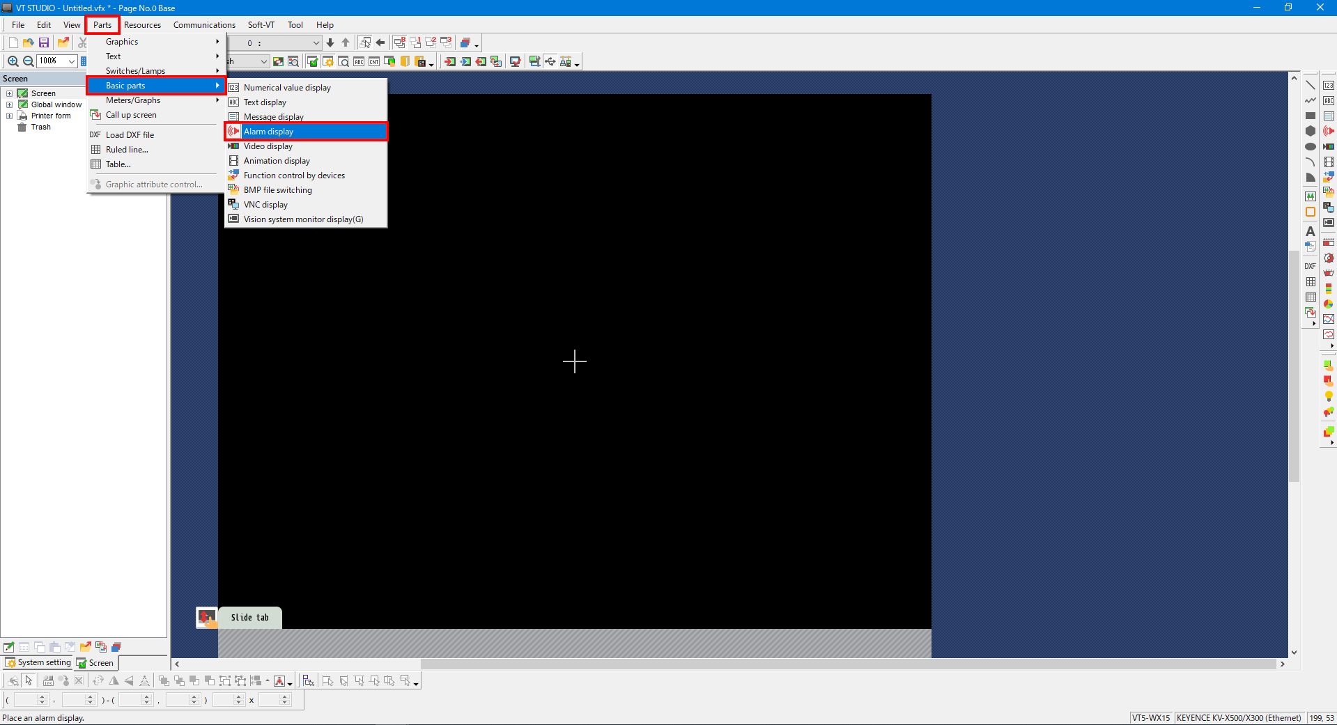
1. From the menu, select [Parts] -> [Basic parts] -> [Alarm display], and then place an alarm display part.
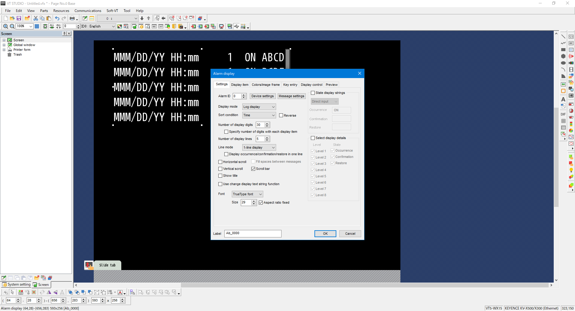
2. On the “Settings” tab, set the number of digits and the number of rows.
| Item | Setting |
|---|---|
| Display mode | Select “Log display” to display the alarm that is occurring. |
| Sort condition | Select the sorting condition to use when multiple alarms have occurred. |
| Number of display digits | Specifies the number of digits to display on a single row. The number of digits includes all the displayed information such as the date and time and the number of occurrences. |
| Number of display lines | Specifies the number of rows to display on the alarm display part. |
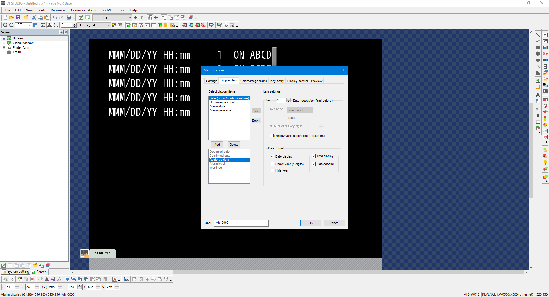
3. On the “Display Item” tab, select the items to display.
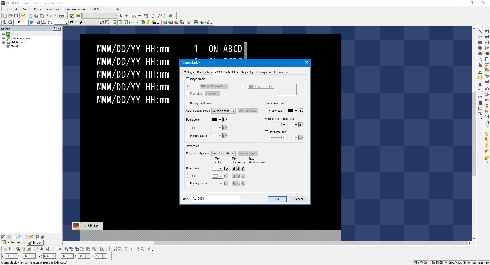
4. On the “Colors/Image frame” tab, set the background color and the text color.
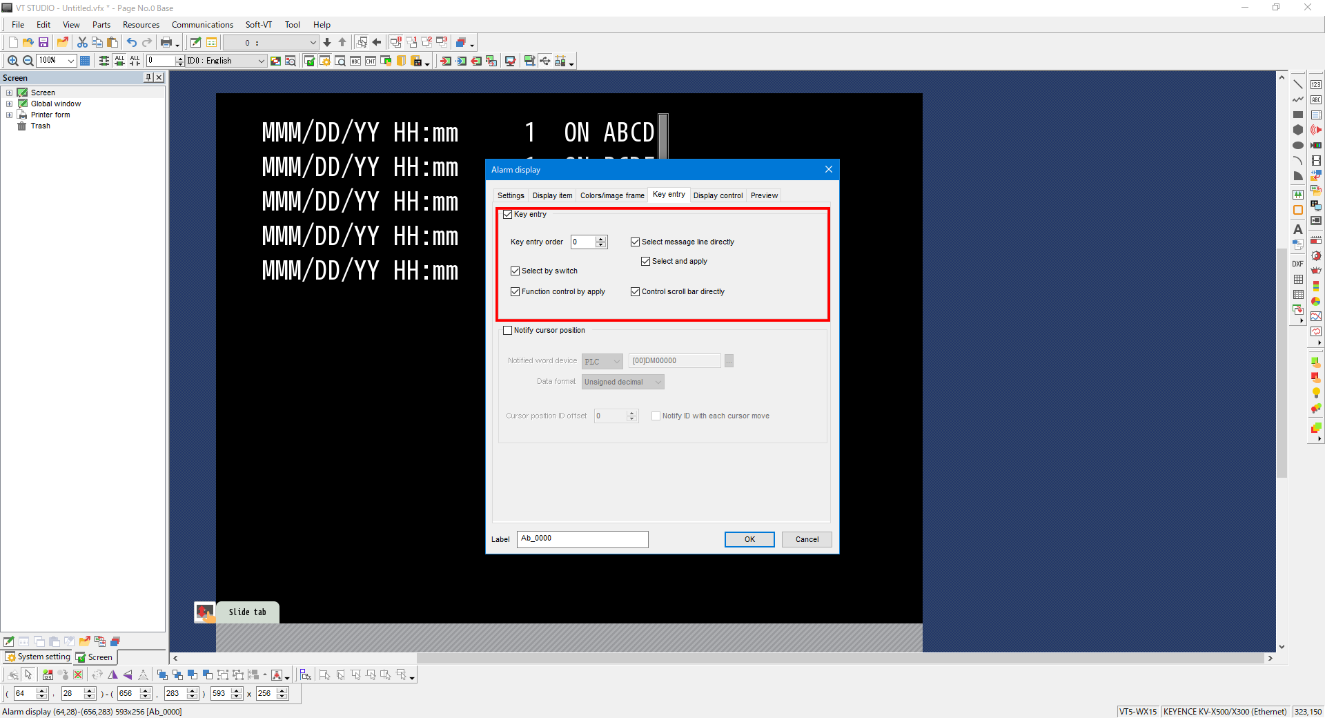
5. On the “Key entry” tab, configure the settings as shown below. With the following settings, you can tap the alarm that has occurred to display a pop-up window containing the countermeasure for the alarm.
Alarm trigger settings
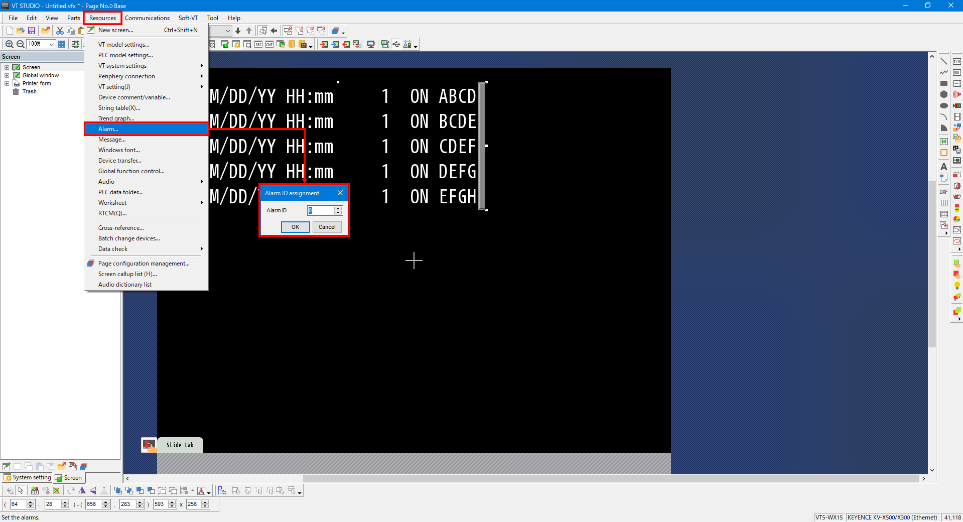
6. From the menu, select [Resources] -> [Alarm]. Enter an alarm ID.
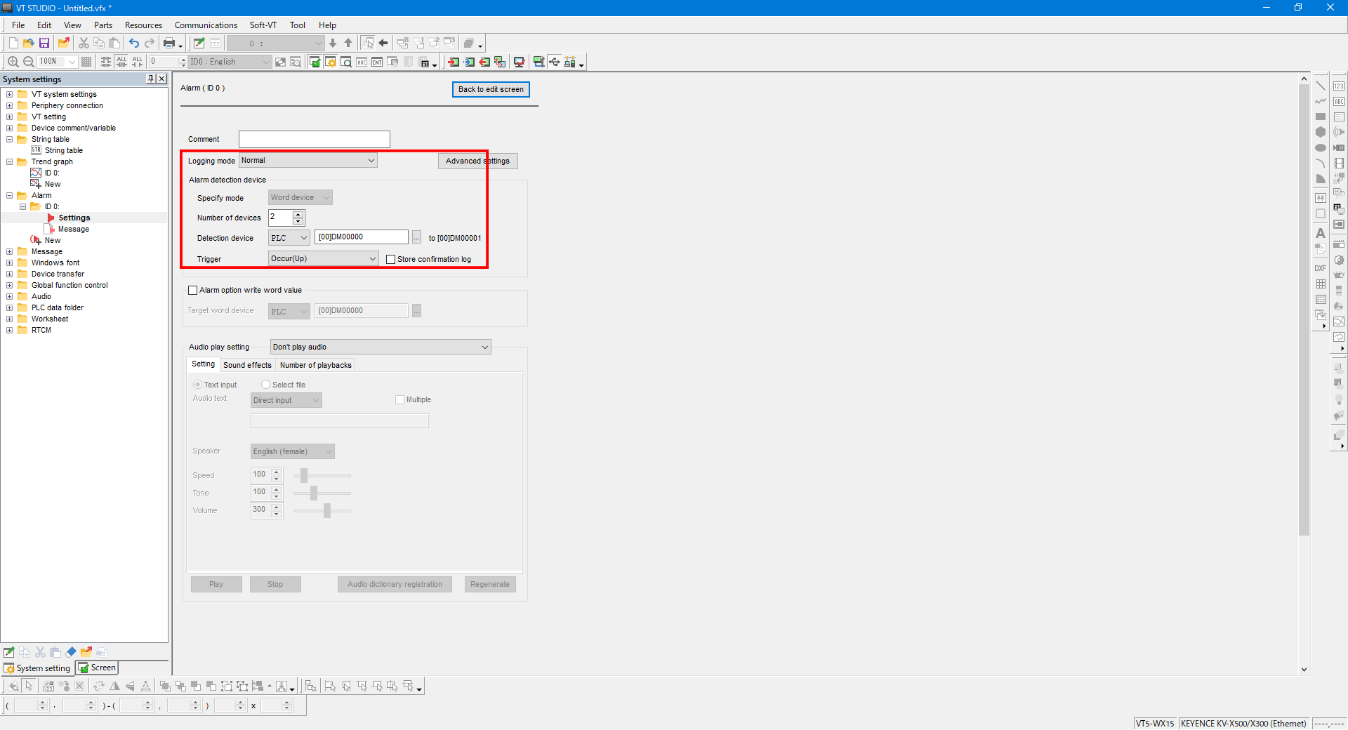
7. Specify the alarm trigger device. When “Logging mode” is set to “Normal,” you can only specify word devices.
To specify bit devices, select “Expanded (continuous device specification)” or “Expanded (individual device specification).”
8. Click “Message,” and then enter the message to display when the alarm occurs.
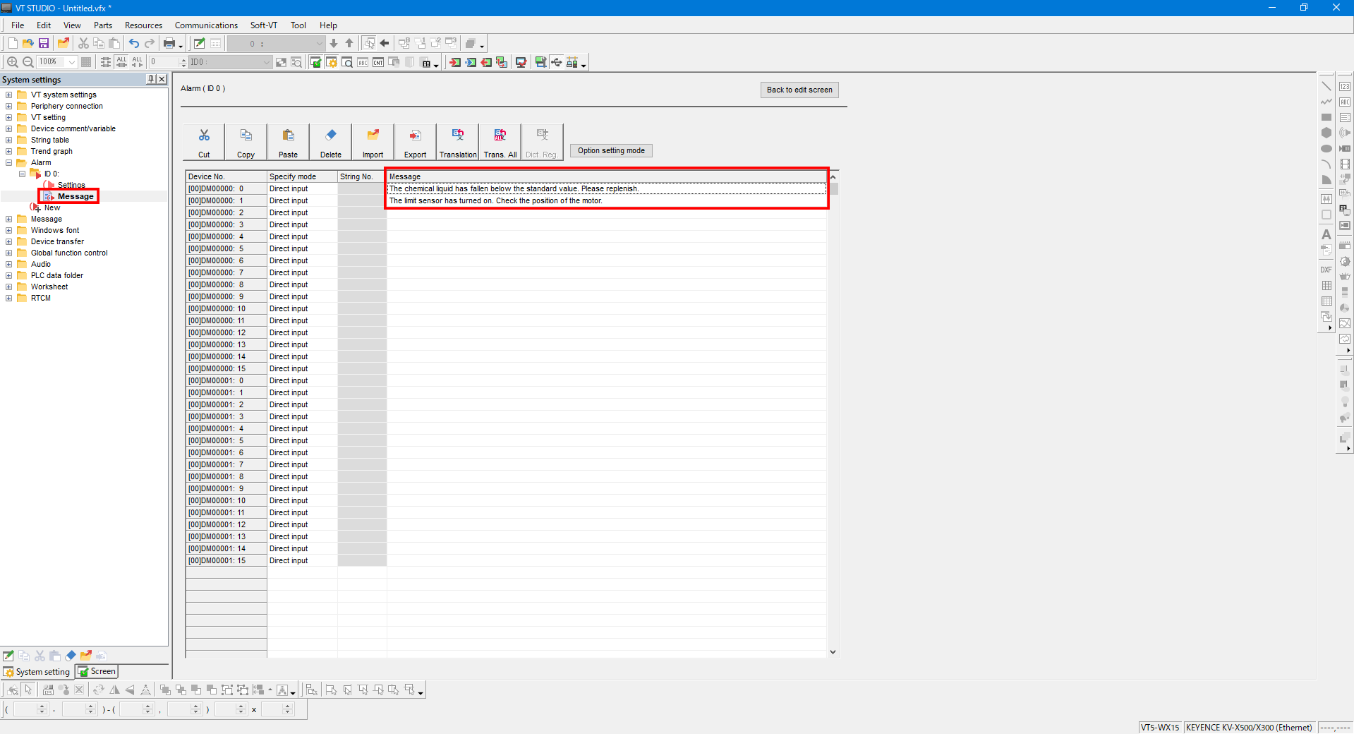
9. Click [Option setting mode] to enable the setting of the detailed options when an alarm row is tapped.
Double-click the target alarm to display the [Alarm option], and then configure the settings as shown below.
| Item | Setting |
|---|---|
| Function | Global window display |
| Window No. | Window number of the global window containing the countermeasure for the target alarm |
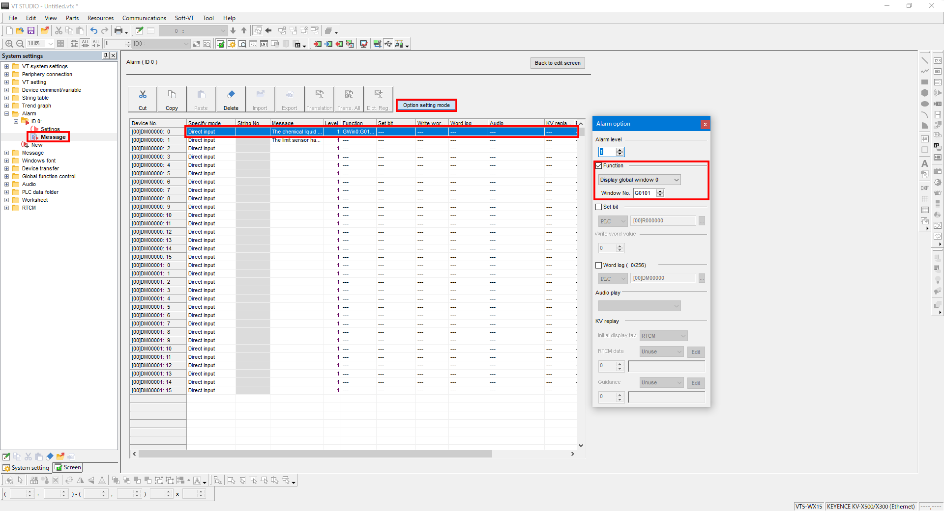
With the above settings, you can display a pop-up window containing the countermeasure by tapping the alarm row when an alarm occurs.
