Vision Systems
- Vision System with Built-in AI VS series
- Intuitive Vision System CV-X series
- Customizable Vision System XG-X series
- GigE camera and lighting for PC-based machine vision VJ series
- Inline 3D Inspection 3D Vision series
- 3D Vision-Guided Robotics 3D VGR series
- Line Scan Technology Line Scan series
- 2D Vision-Guided Robotics 2D VGR series
- LED Lighting CA-D series
- Lenses (for Machine Vision) CA-L series
- Machine Vision System Database VisionDatabase series
- Automotive
- Automation Equipment/Machine Building
- Electric Vehicles
- Medical Device Manufacturing
- Food/Beverage Packaging
- Semiconductor/Manufacturing Electronics
- Vision-Guided Robotics
- Solar
- Logistics
- Commodities
- Paper Manufacturing
- Machine Tools
- Electronic Device
- Printing
- Mining/Metals
- Fabric/Textile
- Tobacco
- Marine
- Aerospace
Vision Measurement for Dimension Inspection
Dimension inspection in the modern industry relies on machine vision systems, to conduct dimensional inspections of manufactured parts and other goods. Here we’ll discuss vision measurement for dimension inspection, its advantages, as well as technical aspects of the vision measurement systems KEYENCE has to offer.
Dimension Measurement
Dimension inspection is a type of appearance inspection. It plays an important role in making pass/fail judgments of whether parts or products have been worked or assembled according to specifications. These dimension inspections can be automated with image processing:
- Measuring maximum/minimum dimensions of parts or products
- Measuring maximum/minimum/average inner or outer diameters or center coordinates of O rings
- Measuring roundness or angle of the tips of metal parts
- Measuring positions of edges and labels
- Measuring widths of sheet/film products
Dimension measurement is the basis of inspection; however, it was difficult to introduce because it required large amounts of time and effort. With the expansion of factory automation (FA), dimension measurement using image processing has increased. This page introduces the basic principle, advantages and practical applications of dimension measurement using image processing.
We’re here to provide you with more details.
Reach out today!

Advantages of Introducing Image Processing
In general, the dimensions of parts and products are measured with microgauges or calipers or checked with inspection jigs to ensure that there is no variation in accuracy. Measurements using instruments such as microgauges or calipers inevitably involve errors due to individual differences among workers and measurement conditions. The result of checks with inspection jigs can be used for pass/fail judgment of whether the product is within the tolerance range or not. However, it does not show accurate measured values.
Other methods of dimension measurement include optical comparators, GD&T and profile measurement systems, and 3D measurement systems. They share the problems of requiring manual operation, and being both time consuming and expensive.
With image processing, various dimensions can be obtained from captured images. It is easy to measure the dimensions of various sections of parts and products based on this data and judge whether they are within tolerances. Another advantage is that you can measure angles or circle roundness simultaneously with the lengths of various sections, and save them as numerical data.
100% Inspection for Preventing Oversight and Outflow of Defective Workpieces
Dimension inspection using various measurement systems and jigs tends to require many offline processes. Consequently, 100% inspection incurs significant labor and costs. On the other hand, sample inspection has the possibility of inspection omission or outflow of defective workpieces. Dimension inspection using an image processing system can achieve inline dimension measurement of all targets. This ensures stable product quality while keeping costs down.
Faster Inspection for Improved Productivity
Inline dimension measurement of parts and products allows significant reduction of inspection time. Image processing systems make inspection faster and contribute to productivity improvement.
Storage and Management of Quality Information
Jig-based dimension inspection does not provide accurate measurement data. It only checks whether the dimension is within the tolerance range or not. Dimension inspection using image processing provides not only pass/fail judgment results but also numerical data of the accurate dimensions of multiple sections, and this data can be easily saved and managed. Such information can also be used effectively for traceability management or process improvement.
Discover more about this product.
Click here to book your demo.

Basics of Dimension Measurement: Measurement Based on Edge Detection
Measurement based on edge detection is generally used for dimension inspection using image processing. This section explains pixel resolution, the basics of sub-pixel processing, and the principle of edge detection to help understand edge detection.
Relationship Between Image Resolution and Judgment Tolerance
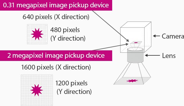
The image pickup device of machine vision consists of an array of pixels. In dimension measurement, you can calculate the dimension tolerance based on this number of pixels and the field of view. An important factor for the calculation is pixel resolution, which is the actual length that corresponds to a single pixel of the image pickup device. The pixel resolution can be calculated with this formula:
Pixel resolution = Field of view in the Y direction [mm] / Number of pixels of the image pickup device in the Y direction [pixels]
For example, assume you use a 0.31 megapixel camera and a 2 megapixel camera. The number of pixels in the Y direction is 480 for the 0.31 megapixel camera and 1200 for the 2 megapixel camera.
When the field of view is 100 mm:
[0.31 megapixel]
Pixel resolution = 100 mm / 480 pixels = 0.208 mm/pixel
[2 megapixel]
Pixel resolution = 100 mm / 1200 pixels = 0.083 mm/pixel
[21 megapixel]
Pixel resolution = 100 mm / 4092 pixels = 0.024 mm/pixel
The pixel resolution can be calculated in this way. The table below shows reference pixel resolution values of cameras used in typical image processing systems, from 0.31 to 21 megapixels.
Pixel resolution Reference value
| Field of view (Y direction)[mm] | |||||||||
|---|---|---|---|---|---|---|---|---|---|
| Number of pixels of the camera | 1 | 5 | 10 | 20 | 30 | 50 | 100 | 200 | 500 |
| 0.31 megapixel | 0.002 | 0.01 | 0.021 | 0.042 | 0.063 | 0.104 | 0.208 | 0.417 | 1.042 |
| 2 megapixel | 0.0008 | 0.004 | 0.008 | 0.017 | 0.025 | 0.042 | 0.083 | 0.167 | 0.417 |
| 5 megapixel | 0.0005 | 0.002 | 0.005 | 0.01 | 0.015 | 0.024 | 0.049 | 0.098 | 0.244 |
| 21 megapixel | 0.0002 | 0.001 | 0.002 | 0.005 | 0.007 | 0.012 | 0.024 | 0.049 | 0.122 |
Scroll
*Number of pixels in the Y direction of the CCD of a 0.31 megapixel sensor = 480 pixels
*Number of pixels in the Y direction of the CCD of a 2 megapixel sensor = 1200 pixels
*Number of pixels in the Y direction of the CCD of a 5 megapixel sensor = 2050 pixels
*Number of pixels of the image pickup device in the Y direction of a 21 megapixel camera = 4092 pixels
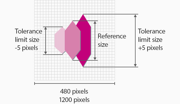
In dimension inspection, the tolerance used as a threshold for differentiating good and defective workpieces is usually calculated in units of ±5 pixels. This is based on the assumption that the number of pixels that ensures stable tolerance judgment is about 10 times the repeatability. Since the repeatability of typical machine vision is about 0.1 pixel under ideal conditions, the practical repeatability is considered to be 0.5 pixel with some margin included. Multiplying this number by 10 yields ±5 pixels, and this value can be regarded as the minimum unit for tolerance setting. You can use this value to calculate the actual dimension tolerance with this formula:
Actual dimension tolerance [mm] = Pixel resolution (field of view in the Y direction) [mm] / Number of pixels of CCD in the Y direction × 5 pixels
[0.31 megapixel]
Dimension tolerance = 0.208 mm/pixel × 5 pixels = 1.04 mm
[2 megapixel]
Dimension tolerance = 0.083 mm/pixel × 5 pixels = 0.415 mm
[21 megapixel]
Dimension tolerance = 0.024 mm/pixel × 5 pixels = 0.12 mm
You need to select machine vision and field of view that provides the required accuracy.
Tolerance judgment value
| Field of view (Y direction)[mm] | |||||||||
|---|---|---|---|---|---|---|---|---|---|
| Number of pixels of the camera | 1 | 5 | 10 | 20 | 30 | 50 | 100 | 200 | 500 |
| 0.31 megapixel | 0.01 | 0.05 | 0.1 | 0.2 | 0.3 | 0.5 | 1.0 | 2.1 | 5.2 |
| 2 megapixel | 0.004 | 0.02 | 0.04 | 0.08 | 0.1 | 0.2 | 0.4 | 0.8 | 2.1 |
| 5 megapixel | 0.002 | 0.01 | 0.02 | 0.05 | 0.07 | 0.1 | 0.2 | 0.5 | 1.2 |
| 21 megapixel | 0.001 | 0.006 | 0.01 | 0.02 | 0.04 | 0.06 | 0.1 | 0.2 | 0.6 |
Scroll
Basics of Sub-Pixel Processing
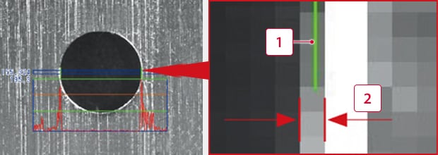
Edge measurement value (pixel)
As explained above, the pixel resolution is the actual dimension value of one pixel. In reality, however, dimension measurement using image processing can show dimensions to units less than a pixel through approximate calculation. This is called sub-pixel processing.
A sub-pixel is a unit smaller than a pixel. For example, KEYENCE's image processing offers dimension data in units of 1/1000 pixel.
-
1The position of the edge is calculated in units less than a pixel.
-
2Width of one pixel
Principle of sub-pixel processing
The sub-pixel processing detects an edge where the contrast changes between bright and dark, converts it into a projection waveform, and then performs differential processing. The peak of the differential waveform is determined as an edge point.

Curious about our pricing?
Click here to find out more.
Dimension Measurement Based on Edge Detection
Edge detection is especially important for dimension measurement using high pixel resolution (high precision). This section describes the basic flow of edge detection.
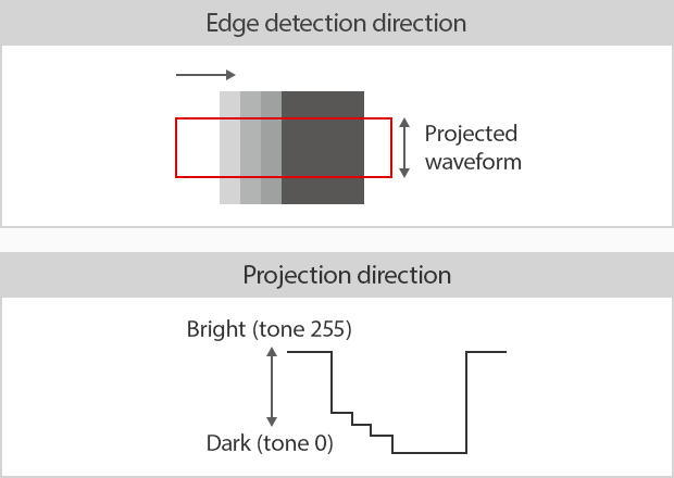
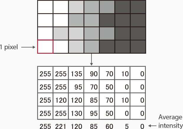
1. Projection
Scan the target perpendicularly to the detecting direction to obtain the average shade of the projection lines. The average shade waveform of the projection lines is called a projection waveform.
2. Differentiation
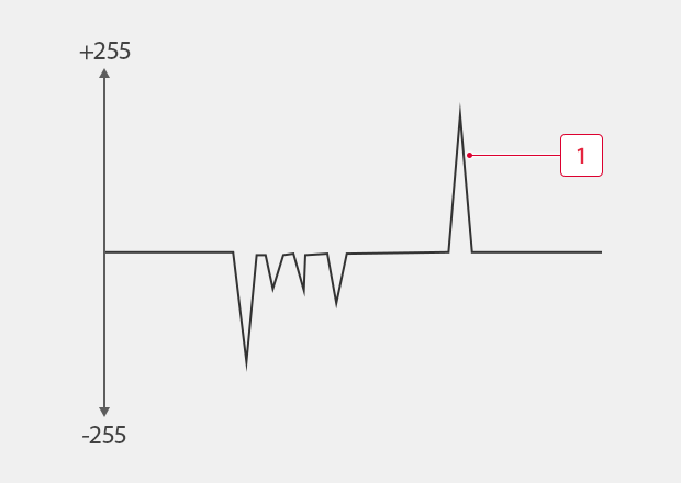
The differentiation of the projection waveform shows larger differential values for points that might be edges. Differentiation is a process for finding changes in shades (gradation levels).
-
1Differential waveform (edge strength waveform)
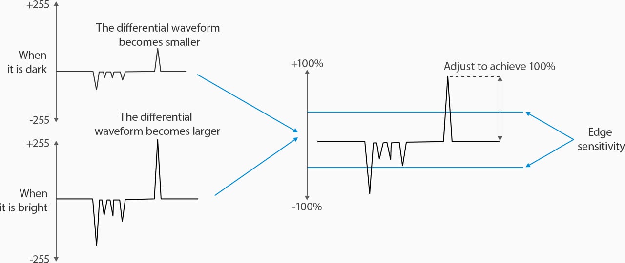
3. Correction to Make the Maximum Differential Value 100%
Apply correction so that the maximum differential value and absolute value become 100% to stabilize the edge. The peak of the differential waveform that exceeds the specified edge sensitivity is determined as an edge point.
Edge detection is not affected by changes in illumination intensity becase the internal detection conditions remain the same.
4. Sub-Pixel Processing
Enlarged image
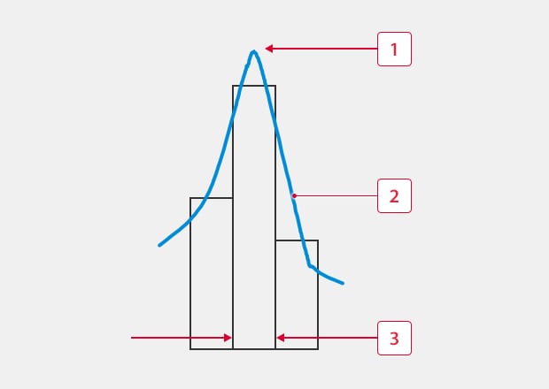
Calculate the waveform of three pixels, one at the peak of the differential waveform and two adjacent pixels, and measure the edge position in units of 0.001 pixel.
-
1Obtain the peak position from the intensity of adjacent pixels.
-
2Differential waveform
-
31 pixel
See the benefits firsthand by signing up for a free trial now.
Free Trial
Practical Applications
As factory automation increases, saving time in inspection has become a challenge, and the same holds for dimension measurement. Measuring using image processing has become the main technique for this kind of process improvement.
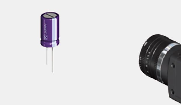
Inspection of Various Dimensions of Chip Capacitors
In addition to the diameter and length of the capacitor body, its parts can be divided into segments to perform edge position detection and obtain the minimum diameter of a narrowing part or the length or bend of a lead wire. The dimensions of each part can be measured accurately.
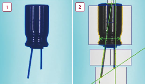
Inspection screen
-
1Original image
-
2Processed image
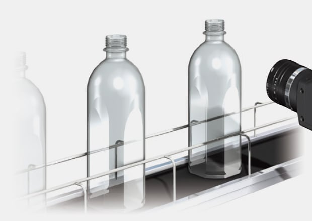
Dimension Measurement of Bottle Mouths
Dimensions can be measured accurately even when used inline. For example, you can capture an image of a PET bottle moving on a line from the side and measure the dimension of the bottle neck ring to detect defective molding, incorrect type, or assembly failure. This kind of Inline dimension inspection improves efficiency.
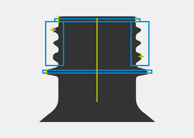
Inspection screen
Curious about our pricing?
Click here to find out more.

Advantages of Vision Measurement for Dimensional Measurement
Vision measurement systems for dimensional measurement come with their own unique advantages, especially over the traditional measurement methods. They’re exceptionally accurate, precise, and capable of detecting even the most minute of details and variations in object dimensions.
This precision, which is crucial to aerospace, automotive, and electronic industries (but many other industries as well), is one of the main benefits of visual measurement systems. However, their speed and accuracy aren’t the only benefits.
The lack of physical contact is another benefit that significantly reduces the risk of damage to the object whose physical properties are being measured, which is particularly important for fragile or thin objects, such as films or semiconductors. This makes vision measurement systems not only safe but also very cost-efficient, as they typically take dimensional measurements at a much faster rate.
Additionally, vision measurement systems typically transmit their data to a data acquisition system, which then processes the data and stores it for subsequent analysis. The combination of these benefits makes the visual measurement systems suitable for manufacturing processes associated with high-speed production without having to sacrifice precision.
KEYENCE's Vision System with Built-In AI has some specific benefits that set it apart from other vision measurement systems. One of the main advantages is its ability to adjust focus and field of view with just one click. This feature eliminates the need for lens selection or changes, making setup and operation much simpler and quicker.
Another key benefit of the AI software is its user-friendly interface, allowing users to create both simple and sophisticated inspections. The software package can also analyze and visualize data easily and quickly, providing users with accurate information.
Contact us to learn more about how our advanced technology can help take your business to the next level.
Contact Us
Dimensional Measurement Using Vision Systems FAQs
How Does Vision Measurement for Dimensions Work?
The inner workings of machine vision systems for dimensional measurement depend on various factors, but they all rely on non-contact measurement methods. This implies the use of various laser technologies or photogrammetry.
For example, some laser scanners rely on confocal laser technology for vision measurements, while others rely on laser triangulation displacement. Both technologies can measure the distance between the sensor and thus derive its dimensions. Photogrammetry relies on the use of highly advanced 3D cameras, and optical micrometers rely on lasers or thru beam sensors.
What Industries Benefit From Dimensional Measurement Using Vision Systems?
Many industries benefit from dimensional measurements using vision systems, primarily industries that require non-contact measurements due to the sensitive nature of their products or industries that rely on high-precision manufacturing.
Vision systems are being increasingly adopted by more industries, including the manufacturing industry (with the automotive and aerospace at the forefront), semiconductors and electronics, pharmaceuticals, food and beverage, plastics, metalworking, logistics, and many others in which accurate and precise measurements are key.
How Can Vision Measurement Improve Dimensional Inspections?
Vision measurement systems improve dimensional inspections in several different ways, depending on the application requirements. One of the ways vision measurement systems improve dimensional inspections is due to their enhanced accuracy and precision, often down to the single-digit µm range.
Additionally, since they’re non-contact measurement methods, vision measurements don’t physically touch the object being measured, eliminating the risk of damaging the part or affecting a part in a way that would subsequently affect dimensional measurements.
We’re here to provide you with more details.
Reach out today!

Related Downloads
This guide is a compilation of trivia pertaining to vision systems. Figures are used to provide easy-to-understand explanations of principles and characteristics for items ranging from lenses, image capturing, lighting, and color to communication and preprocessing. This guide is a must-read for anyone wanting to learn all about vision systems.
Related Products
Industries
- Automotive
- Automation Equipment/Machine Building
- Electric Vehicles
- Medical Device Manufacturing
- Food/Beverage Packaging
- Semiconductor/Manufacturing Electronics
- Vision-Guided Robotics
- Solar
- Logistics
- Commodities
- Paper Manufacturing
- Machine Tools
- Electronic Device
- Printing
- Mining/Metals
- Fabric/Textile
- Tobacco
- Marine
- Aerospace

