
Main Unit Model: GS-M50P
PNP
| OSSD operation | Lock link mode |
|---|---|
| Interlock function | Automatic only |
| EDM function | N/A |
| Applicable model | Main unit |
|---|---|
| Hinged door, terminal block | GS-M50P |
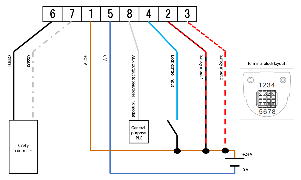
| Required | Pin | Color | Icon above | Function |
|---|---|---|---|---|
| 1 | Brown |  |
+24 V | |
| 5 | Blue |  |
0 V | |
| 6 | Black |  |
OSSD1 | |
| 7 | White |  |
OSSD2 | |
| 2 | Red/black |  |
Safety input 1 | |
| 3 | Red/white |  |
Safety input 2 | |
| 8 | Gray |  |
AUX output (open/close link mode) | |
| 4 | Light blue |  |
Lock control input |
- The required wiring ensures that the unit can be operated without entering the error state.
- The icons in the above figure match the wire colors of the connector type. You do not have to use wires of the same colors.
