KV-X Series × SR-X Series
EtherNet/IP™ Connection Guide
Return to KV Series Connection Guide
KV-X Series × SR-X Series EtherNet/IP™ Connection Guide
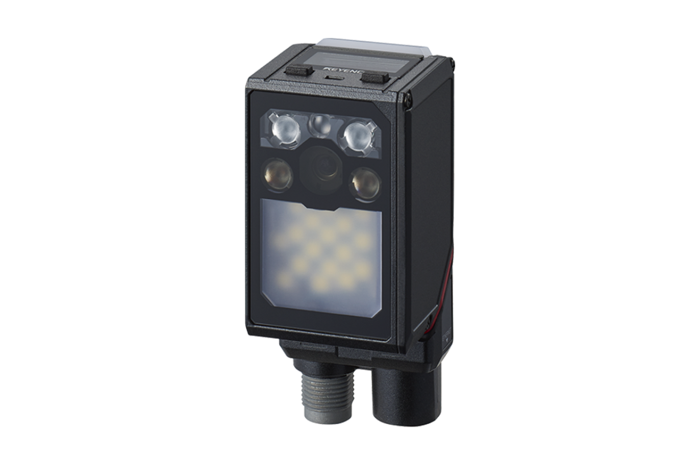
SR-X Series

Supported code readers
- SR-X Series
- SR-2000/1000 Series
- SR-5000 Series
- SR-750/D100 Series
- SR-700 Series (via the N-L20)
- BL-1300 Series (via the N-L20)
Contents
Step 1 : Equipment Required for Connections
In this guide, communication with the KV Series is explained as an example.
When using other units, read this guide with these other units in mind.
Prepare the following equipment.
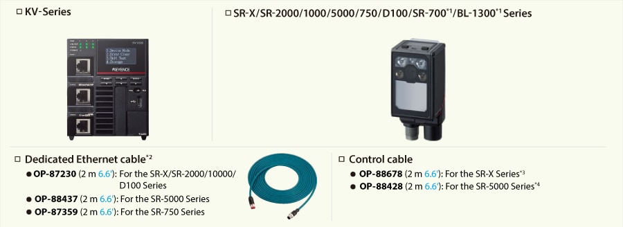
※1 The N-L20 (sold separately) is required when using the SR-700/BL-1300 Series.
※2 This is the cable for connecting the code reader and the PLC. This dedicated cable is not necessary when using the N-L20.
※3 This is the cable for connecting a 24 V power supply, I/O terminals, and an RS-232C port.
※4 When using the SR-5000 Series, use the OP-88437 or a similar option for the power supply cable.
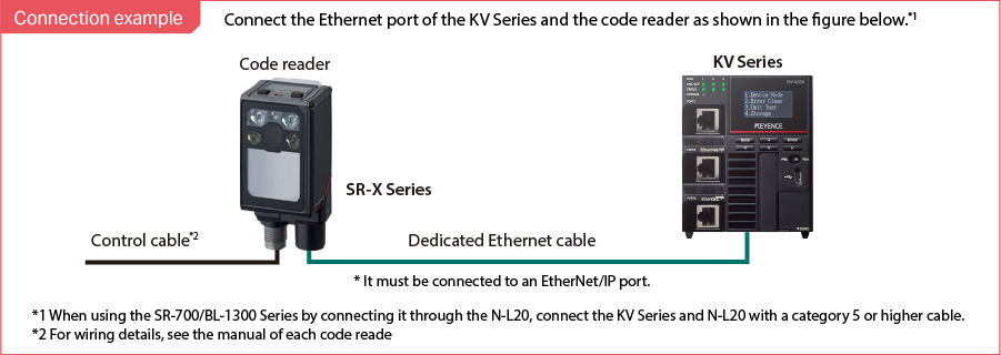
Step 2 : Code Reader Settings
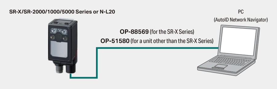
< SR-X/SR-2000/1000/5000 Series, SR-700/BL-1300 Series (via the N-L20) >
Use AutoID Network Navigator to configure the communication settings of the SR-X/SR Series.
* For the SR-750/D100 Series, see “< SR-750/D100 Series >”.
1. Use a USB cable to connect the PC and the SR-X/SR-2000/1000/5000 Series or the N-L20.
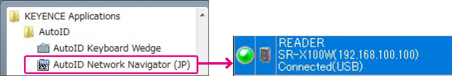
2. Start AutoID Network Navigator from [All Programs].
If the following information is displayed, the connection has been established.
3. Set the IP address and the subnet mask.
Configure these settings to match the usage environment. In this guide, the settings are configured as in the following example.
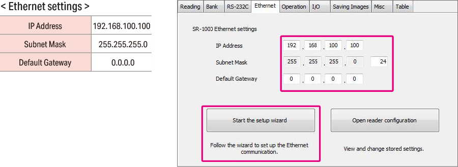
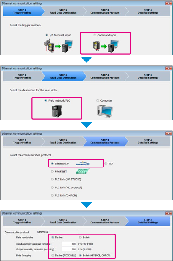
4. Click [Start the setup wizard], and then configure the settings as shown below.
5. Transmit the settings.
6. Click the blue lamp to disconnect from the code reader.
It is not possible to communicate with the PLC while connected to AutoID Network Navigator.

This completes the code reader settings.
< SR-750/D100 Series >
Use AutoID Network Navigator to configure the communication settings of the SR-750/D100 Series.
* For the SR-X/SR-2000/1000/5000 Series and SR-700/BL-1300 Series (via the N-L20), see ”< SR-X/SR-2000/1000/5000 Series, SR-700/BL-1300 Series (via the N-L20) >”.
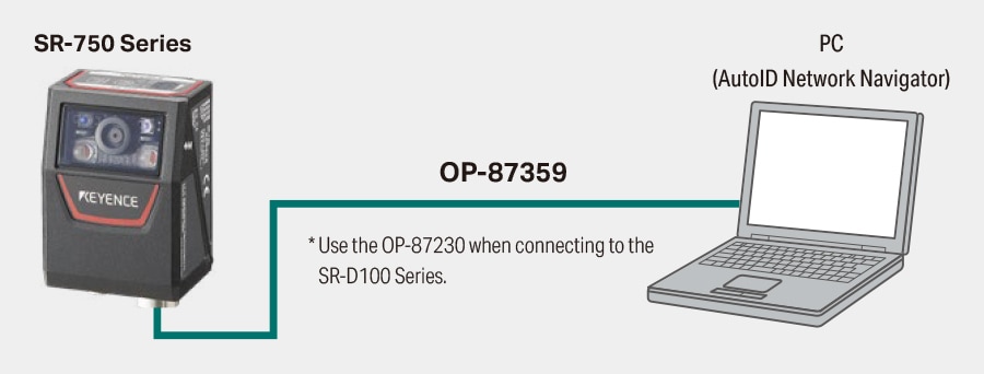
1. Use a dedicated Ethernet cable to connect the PC and the SR-750/D100 Series.
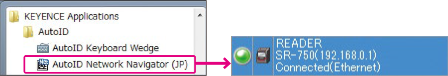
2. When you start AutoID Network Navigator, it will automatically search for the code readers on the network.
If the following information is displayed, the connection has been established.
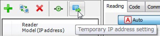
If no code readers are found, use the following procedure to set a temporary IP address and establish a connection.
(1) Click the [Temporary IP address setting] icon to display the [Temporary IP Address Setting] dialog box.
(2) Operate the code reader switches to start BOOTP operation.
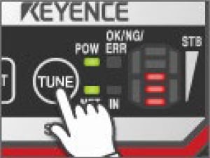
SR-750 Series
Hold down the TUNE switch for at least 5 seconds until LEDs 1 to 4 light.
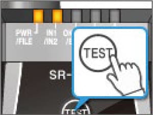
SR-D100 Series
Hold down the TEST switch for at least 5 seconds until LEDs 1 to 4 light.
When the code reader is found, the following window appears.
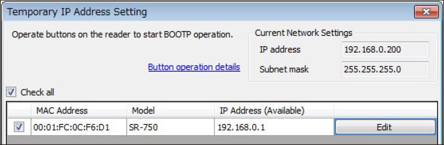
(3) Click [OK] to assign the temporary IP address.
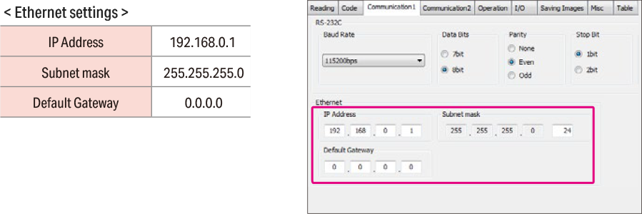
3. Select the [Communication 1] tab, and then set the IP address and subnet mask.
Configure these settings to match the usage environment. In this guide, the settings are configured as in the following example.
4. Select the [Communication 2] tab, and then configure the communication settings.
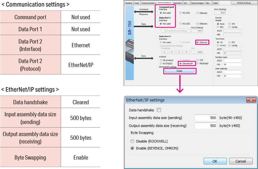
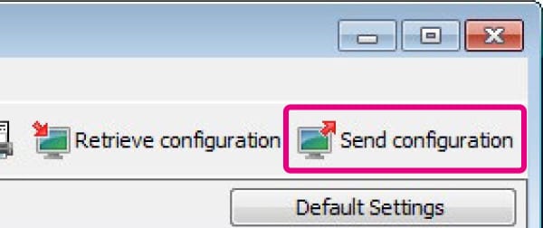
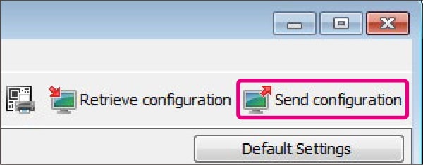
5. Transmit the settings.
6. Click the blue lamp to disconnect from the code reader.
It is not possible to communicate with the PLC while connected to AutoID Network Navigator.

This completes the (SR-750/D100 Series) code reader settings.
Step 3 : KV-X Series Connection Settings
This section explains how to connect with a fictitious device called "Vendor Series". Replace the "Vender Series" with the device to be connected.
One point
For the KV Series with a CPU function version of 2.0 or later, variables can be assigned to the connection of EtherNet/IP.
When assigning variables to the connection of EtherNet/IP®, check the box of “Displays the variable setting dialog when updating the EtherNet/IP settings (E)” for “Other settings” of “System settings” on the “CPU system settings” dialog.
The “CPU system settings” dialog is displayed by selecting [Display (V)] ⇒ [CPU system settings (P)] from the ”KV STUDIO” menu.
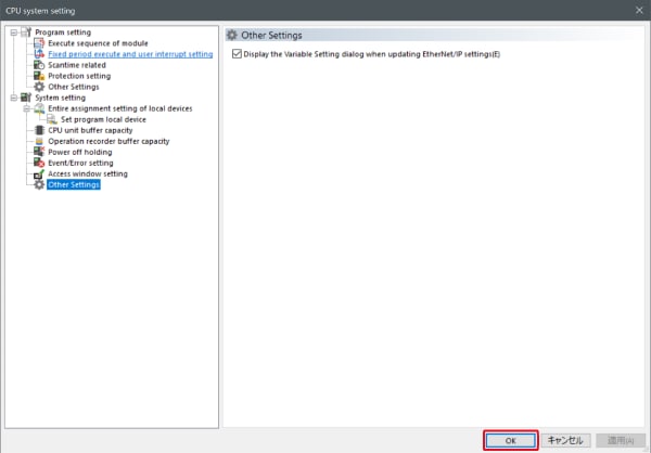
When the box of "Displays the variable setting dialog when updating the EtherNet/IP settings (E)" is checked, at the timing when the EtherNet/IP setting is updated and the changed content of the unit editor is confirmed, a dialog to assign variables to the connection is displayed.
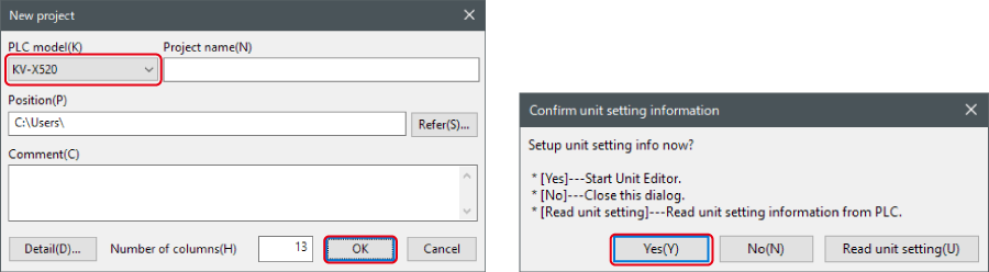
1. Start up the KV STUDIO and create a new project. Set the model option to “KV-X520” and click [OK].
A [Confirm unit configuration setting] dialog box is displayed. Click [Yes (Y)].
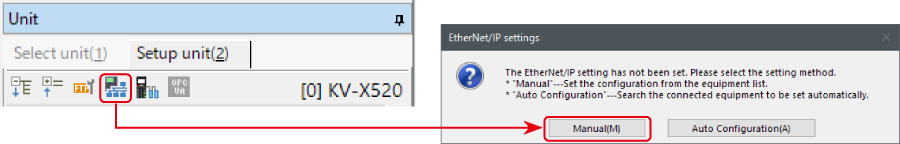
2. The unit editor is displayed. On the “Setup unit(2)” tab, click the icon of EtherNet/IP setting. A configuration type selection dialog box is displayed. Click [Manual (M)].
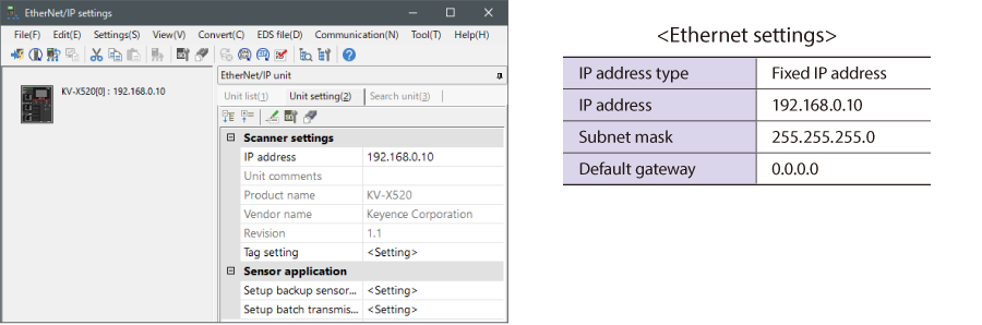
3. On the “Unit setting (2)” tab, set the IP address for KV-X Series. In this example, configure the setting as shown below.
* Step 4 needs to be performed to import a sensor setting file. When the sensor setting file has already been imported, proceed to Step 5.
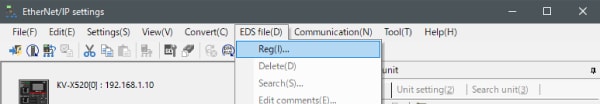
4. Select [EDS file (D)] → [Reg (I)] to import the KEYENCE sensor setting file(ez1 file) or EDS file.
* Download the sensor setting file from the KEYENCE website.
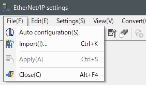
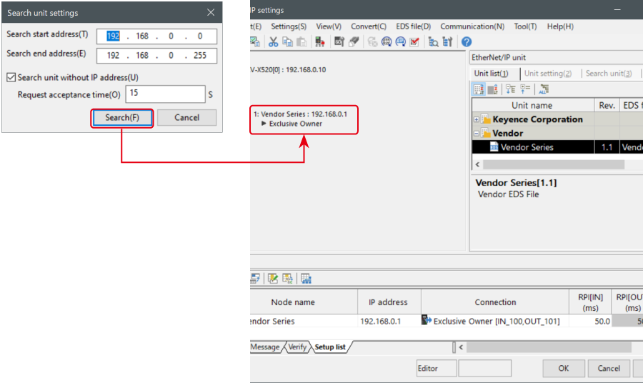
5. With the KV-X Series and the EtherNet/IP devices connected using the Ethernet cable, select [File (F)] → [Auto configuration (S)] on the [EtherNet/IP settings] window.
6. When the configuration on the unit editor differs from that of the actual device, a dialog for confirming transfer of the project is displayed. With the PC and KV-X Series connected using the USB cable, click [Yes (Y)].
7. When transfer of the project is completed, the [Search unit settings] dialog is displayed. Then click [Search (F)]. After the auto configuration is completed, "Vendor Series" is automatically registered. Then click [OK] to close the [EtherNet/IP settings] window.
8. Click [OK] on the unit editor to exit.
One point
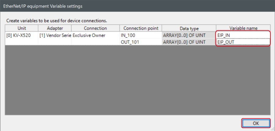
When the box of "Displays the variable setting dialog when updating the EtherNet/IP settings (E)" is checked, the [EtherNet/IP equipment Variable settings] dialog is displayed.
Enter the name of variable assigned to the connection, and click [OK].
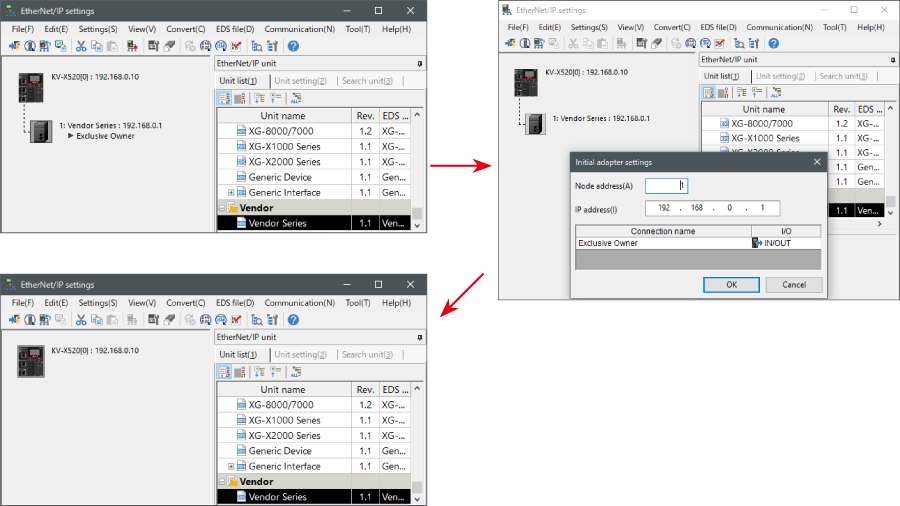
- The way of Device Configuration Settings manually
In the [Unit list (1)] tab of “EtherNet/IP Settings”, drag and drop "Vendor Series" and create a device configuration.
Transferring and Monitoring Setting Data
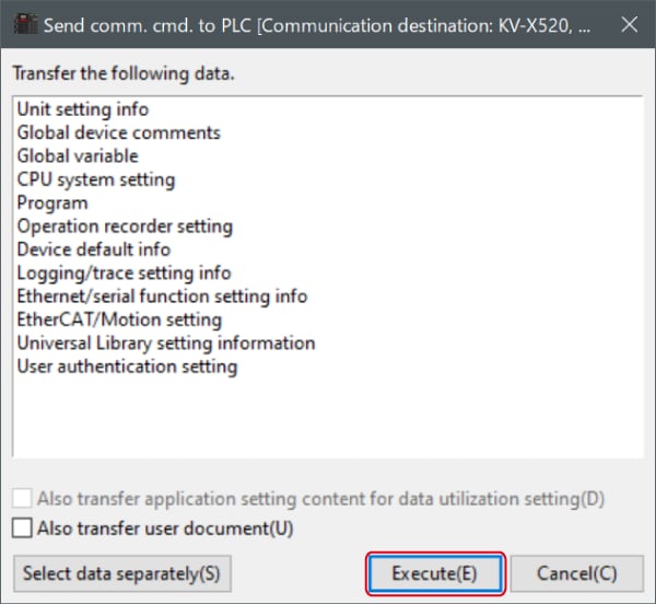
1. From the menu, select [Monitor/Simulator (N)] > [Transfer to PLC (W) → Monitor mode (C)].
In the [Send comm. cmd. to PLC] dialog box, click [Execute(E)].
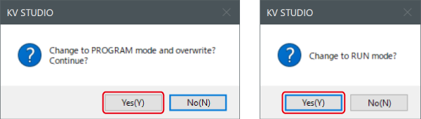
2. If the following dialog box is displayed before and after transferring the data, click [Yes] both times.
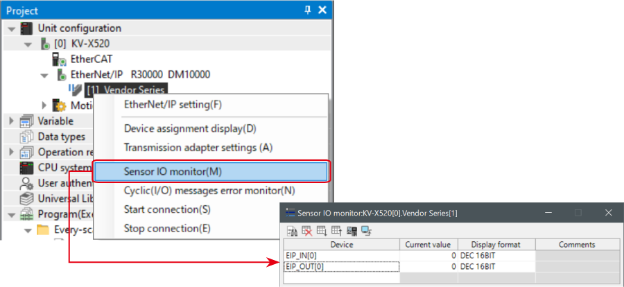
3. Right-click on “Vender Series” in the workspace, and select [Sensor IO monitor (M)].
Scores and other information can be easily monitored.
One point
The information can also be checked on a graph by starting up the real time chart monitor.
Right-click on “Sensor I/O monitor” and select [Real time chart monitor (H)].
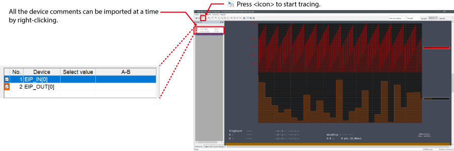
Range adjustment is not required since the real time chart monitor performs scaling automatically.
When Manipulating Parameters with a Program
Changing the Setting Values
The setting values of the sensors can be changed by the following two methods:
A : Change from a PC
B : Change from a ladder program
A : Change from a PC
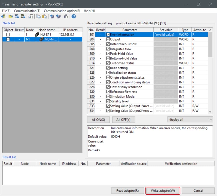
To change the settings from a PC, use the transmission adapter function in KV STUDIO.
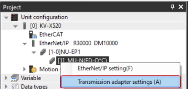
1. Expand the unit configuration in the workspace. Right-click on "Vender Series" and select [Transmission adapter settings (A)].
2. Place a check mark in Setting Value for "Vender Series" and enter the setting value.
Click [Write adapter (W)] to write the setting value to the sensor.
*To read the setting value of a sensor, select [Read adapter (R)].
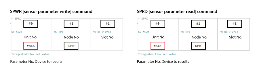
B : Changed from a ladder program
Use message communication to change the setting values from a ladder program.
To perform message communication with KV STUDIO, use the sensor setting commands (SPWR [sensor parameter write] and SPRD [sensor parameter read]).
1. In Editor mode, create a ladder program as shown below.
* For the parameter numbers, refer to Parameter list.
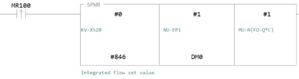
2. Transfer the ladder program.
3. When MR100 is turned on, the setting value is changed.
* Store the setting value in DM4 ([Leading device to store results] + 4).
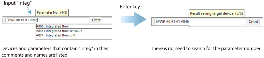
One point
RT (Real-Time) Edit function
When you use a ladder program, you can input device comments or parameter names directly to have input candidates be searched for and displayed automatically.
Reference 1 : Memory Maps
The memory maps of the devices used during cyclic communication and the names of these memory maps are as follows.
SR-X Series/SR-2000 Series
IN: From B000/W000, OUT: From B040/W052
Result data (Input Assemblies)
SR-X Series / SR-2000 Series → KV Series
| Member name | Data Type | Detail |
|---|---|---|
| Error | BOOL | Error |
| ReadDataAvailable | BOOL | Read Data Update Available |
| ReadDataCmplt | BOOL | Read Data Update Complete |
| BufOverflowErr | BOOL | Buffer Overflow Error |
| GeneralErr | BOOL | General Error |
| BUSY | BOOL | BUSY |
| TRG_BUSY | BOOL | TRG BUSY |
| LOCK_BUSY | BOOL | LOCK BUSY |
| MODE_BUSY | BOOL | MODE BUSY |
| ERR_BUSY | BOOL | ERR BUSY |
| READY | BOOL | READY |
| ReadCmplt | BOOL | Reading Complete |
| PrstReadCmplt | BOOL | Preset Reading Complete |
| PrstRegCmplt | BOOL | Preset Registration Complete |
| TuningCmplt | BOOL | Tuning Complete |
| BLOAD_Cmplt | BOOL | BLOAD Complete |
| ExtInstCmplt | BOOL | External Instruction Complete |
| ReadErr | BOOL | Reading Error |
| PrstReadFail | BOOL | Preset Reading Failure |
| PrstRegFail | BOOL | Preset Registration Failure |
| TuningFail | BOOL | Tuning Failure |
| BLOAD_Fail | BOOL | BLOAD Failure |
| ExtInstFail | BOOL | External Instruction Failure |
| IN_Status | ARRAY[0..1] OF BOOL | IN Status |
| OUT_Status | ARRAY[0..2] OF BOOL | OUT Status |
| Unstable | BOOL | Unstable |
| MatchLevelUnstable | BOOL | Matching Level Unstable |
| IEC15415_Unstable | BOOL | ISO/IEC15415 Unstable |
| AIM_DPM_Unstable | BOOL | AIM DPM Unstable |
| AS9132_Unstable | BOOL | SAE AS9132 Unstable |
| IEC15416_Unstable | BOOL | ISO/IEC 15416 Unstable |
| MatchLevel | UINT | Matching Level |
| IEC15415_Grade | UINT | ISO/IEC15415 Grade |
| AIM_DPM_Grade | UINT | AIM DPM Grade |
| IEC15416_Grade | UINT | ISO/IEC 15416 Grade |
| ReadErrCause | UINT | Reading Error Cause |
| PrstReadFailCause | UINT | Preset Reading Fail Cause |
| PrstRegFailCause | UINT | Preset Registration Fail Cause |
| TuningFailCause | UINT | Tuning Fail Cause |
| BLOAD_FailCause | UINT | BLOAD Fail Cause |
| ExtInstErrCause | UINT | External Instruction Error Cause |
| GeneralErrCause | UINT | General Error Cause |
| SlaveID | UINT | Slave ID |
| ReadDataReadyCnt | UINT | Read Data Ready Count |
| ReadDataUpdateCnt | UINT | Read Data Update Count |
| MasterTrgInputCnt | UINT | Trigger Input Count for Master |
| ReadDataSize | UINT | Read Data Size |
| ReadData | STRING[127] | Read Data |
Control data (Output Assemblies)
KV Series → SR-X Series / SR-2000 Series
| Member name | Data Type | Detail |
|---|---|---|
| ReadDataPermitted | BOOL | Read Data Update Permitted |
| ErrorClr | BOOL | Err Clr Transmission Buffer Clr |
| ReadStartReq | BOOL | Reading Start Request |
| PrstReadStartReq | BOOL | Preset Reading Start Request |
| PrstRegReq | BOOL | Preset Registration Start Req |
| TuningStartReq | BOOL | Tuning Start Request |
| BLOAD_Req | BOOL | BLOAD Request |
| ReadCmpltClr | BOOL | Reading Complete Clear |
| PrstReadCmpltClr | BOOL | Preset Reading Complete Clear |
| PrstRegCmpltClr | BOOL | Preset Registration Complete Clr |
| TuningCmpltClr | BOOL | Tuning Complete Clear |
| BLOAD_CmpltClr | BOOL | BLOAD Complete Clear |
| ExtInstCmpltClr | BOOL | Ext. Instruction Complete Clear |
| Bank_BLOAD_Number | UINT | Bank Number/BLOAD File Number |
| PrstDataSize | UINT | Preset Data Size |
| PrstData | STRING[63] | Preset Data |
SR-1000 Series
IN: From B000/W000, OUT: From B040/W052
Result data (Input Assemblies)
SR-1000 Series → KV Series
| Member name | Data Type | Detail |
|---|---|---|
| Error | BOOL | Error |
| ReadDataAvailable | BOOL | Read Data Update Available |
| ReadDataCmplt | BOOL | Read Data Update Complete |
| BufOverflowErr | BOOL | Buffer Overflow Error |
| GeneralErr | BOOL | General Error |
| BUSY | BOOL | BUSY |
| TRG_BUSY | BOOL | TRG BUSY |
| LOCK_BUSY | BOOL | LOCK BUSY |
| MODE_BUSY | BOOL | MODE BUSY |
| ERR_BUSY | BOOL | ERR BUSY |
| ReadCmplt | BOOL | Reading Complete |
| PrstReadCmplt | BOOL | Preset Reading Complete |
| PrstRegCmplt | BOOL | Preset Registration Complete |
| TuningCmplt | BOOL | Tuning Complete |
| BLOAD_Cmplt | BOOL | BLOAD Complete |
| ExtInstCmplt | BOOL | External Instruction Complete |
| ReadErr | BOOL | Reading Error |
| PrstReadFail | BOOL | Preset Reading Failure |
| PrstRegFail | BOOL | Preset Registration Failure |
| TuningFail | BOOL | Tuning Failure |
| BLOAD_Fail | BOOL | BLOAD Failure |
| ExtInstFail | BOOL | External Instruction Failure |
| IN_Status | ARRAY[0..1] OF BOOL | IN Status |
| OUT_Status | ARRAY[0..2] OF BOOL | OUT Status |
| Unstable | BOOL | Unstable |
| MatchLevelUnstable | BOOL | Matching Level Unstable |
| IEC15415_Unstable | BOOL | ISO/IEC15415 Unstable |
| AIM_DPM_Unstable | BOOL | AIM DPM Unstable |
| AS9132_Unstable | BOOL | SAE AS9132 Unstable |
| MatchLevel | UINT | Matching Level |
| IEC15415_Grade | UINT | ISO/IEC15415 Grade |
| AIM_DPM_Grade | UINT | AIM DPM Grade |
| ReadErrCause | UINT | Reading Error Cause |
| PrstReadFailCause | UINT | Preset Reading Fail Cause |
| PrstRegFailCause | UINT | Preset Registration Fail Cause |
| TuningFailCause | UINT | Tuning Fail Cause |
| BLOAD_FailCause | UINT | BLOAD Fail Cause |
| ExtInstErrCause | UINT | External Instruction Error Cause |
| GeneralErrCause | UINT | General Error Cause |
| SlaveID | UINT | Slave ID |
| ReadDataReadyCnt | UINT | Read Data Ready Count |
| ReadDataUpdateCnt | UINT | Read Data Update Count |
| MasterTrgInputCnt | UINT | Trigger Input Count for Master |
| ReadDataSize | UINT | Read Data Size |
| ReadData | STRING[127] | Read Data |
Control data (Output Assemblies)
KV Series → SR-1000 Series
| Member name | Data Type | Detail |
|---|---|---|
| ReadDataPermitted | BOOL | Read Data Update Permitted |
| ErrorClr | BOOL | Err Clr Transmission Buffer Clr |
| ReadStartReq | BOOL | Reading Start Request |
| PrstReadStartReq | BOOL | Preset Reading Start Request |
| PrstRegReq | BOOL | Preset Registration Start Req |
| TuningStartReq | BOOL | Tuning Start Request |
| BLOAD_Req | BOOL | BLOAD Request |
| ReadCmpltClr | BOOL | Reading Complete Clear |
| PrstReadCmpltClr | BOOL | Preset Reading Complete Clear |
| PrstRegCmpltClr | BOOL | Preset Registration Complete Clr |
| TuningCmpltClr | BOOL | Tuning Complete Clear |
| BLOAD_CmpltClr | BOOL | BLOAD Complete Clear |
| ExtInstCmpltClr | BOOL | Ext. Instruction Complete Clear |
| Bank_BLOAD_Number | UINT | Bank Number/BLOAD File Number |
| PrstDataSize | UINT | Preset Data Size |
| PrstData | STRING[63] | Preset Data |
SR-5000 Series
IN: From B000/W000, OUT: From B040/W052
Result data (Input Assemblies)
SR-5000 Series → KV Series
| Member name | Data Type | Detail |
|---|---|---|
| Error | BOOL | Error |
| ReadDataAvailable | BOOL | Read Data Update Available |
| ReadDataCmplt | BOOL | Read Data Update Complete |
| BufOverflowErr | BOOL | Buffer Overflow Error |
| GeneralErr | BOOL | General Error |
| BUSY | BOOL | BUSY |
| TRG_BUSY | BOOL | TRG BUSY |
| LOCK_BUSY | BOOL | LOCK BUSY |
| MODE_BUSY | BOOL | MODE BUSY |
| ERR_BUSY | BOOL | ERR BUSY |
| READY | BOOL | READY |
| ReadCmplt | BOOL | Reading Complete |
| PrstReadCmplt | BOOL | Preset Reading Complete |
| PrstRegCmplt | BOOL | Preset Registration Complete |
| TuningCmplt | BOOL | Tuning Complete |
| BLOAD_Cmplt | BOOL | BLOAD Complete |
| ExtInstCmplt | BOOL | External Instruction Complete |
| ReadErr | BOOL | Reading Error |
| PrstReadFail | BOOL | Preset Reading Failure |
| PrstRegFail | BOOL | Preset Registration Failure |
| TuningFail | BOOL | Tuning Failure |
| BLOAD_Fail | BOOL | BLOAD Failure |
| ExtInstFail | BOOL | External Instruction Failure |
| IN_Status | ARRAY[0..2] OF BOOL | IN Status |
| OUT_Status | ARRAY[0..3] OF BOOL | OUT Status |
| ReadErrCause | UINT | Reading Error Cause |
| PrstReadFailCause | UINT | Preset Reading Fail Cause |
| PrstRegFailCause | UINT | Preset Registration Fail Cause |
| TuningFailCause | UINT | Tuning Fail Cause |
| BLOAD_FailCause | UINT | BLOAD Fail Cause |
| ExtInstErrCause | UINT | External Instruction Error Cause |
| GeneralErrCause | UINT | General Error Cause |
| SlaveID | UINT | Slave ID |
| ReadDataReadyCnt | UINT | Read Data Ready Count |
| ReadDataUpdateCnt | UINT | Read Data Update Count |
| MasterTrgInputCnt | UINT | Trigger Input Count for Master |
| ReadDataSize | UINT | Read Data Size |
| ReadData | STRING[127] | Read Data |
Control data (Output Assemblies)
KV Series → SR-5000 Series
| Member name | Data Type | Detail |
|---|---|---|
| ReadDataPermitted | BOOL | Read Data Update Permitted |
| ErrorClr | BOOL | Err Clr Transmission Buffer Clr |
| ReadStartReq | BOOL | Reading Start Request |
| PrstReadStartReq | BOOL | Preset Reading Start Request |
| PrstRegReq | BOOL | Preset Registration Start Req |
| TuningStartReq | BOOL | Tuning Start Request |
| BLOAD_Req | BOOL | BLOAD Request |
| ReadCmpltClr | BOOL | Reading Complete Clear |
| PrstReadCmpltClr | BOOL | Preset Reading Complete Clear |
| PrstRegCmpltClr | BOOL | Preset Registration Complete Clr |
| TuningCmpltClr | BOOL | Tuning Complete Clear |
| BLOAD_CmpltClr | BOOL | BLOAD Complete Clear |
| ExtInstCmpltClr | BOOL | Ext. Instruction Complete Clear |
| Bank_BLOAD_Number | UINT | Bank Number/BLOAD File Number |
| PrstDataSize | UINT | Preset Data Size |
| PrstData | STRING[63] | Preset Data |
SR-750 Series
IN: From B000/W000, OUT: From B040/W052
Result data (Input Assemblies)
SR-750 Series → KV Series
| Member name | Data Type | Detail |
|---|---|---|
| Error | BOOL | Error |
| ReadDataAvailable | BOOL | Read Data Update Available |
| ReadDataCmplt | BOOL | Read Data Update Complete |
| BufOverflowErr | BOOL | Buffer Overflow Error |
| GeneralErr | BOOL | General Error |
| BUSY | BOOL | BUSY |
| TRG_BUSY | BOOL | TRG BUSY |
| LOCK_BUSY | BOOL | LOCK BUSY |
| MODE_BUSY | BOOL | MODE BUSY |
| ERR_BUSY | BOOL | ERR BUSY |
| ReadCmplt | BOOL | Reading Complete |
| PrstReadCmplt | BOOL | Preset Reading Complete |
| PrstRegCmplt | BOOL | Preset Registration Complete |
| TuningCmplt | BOOL | Tuning Complete |
| ExtInstCmplt | BOOL | External Instruction Complete |
| ReadErr | BOOL | Reading Error |
| PrstReadFail | BOOL | Preset Reading Failure |
| PrstRegFail | BOOL | Preset Registration Failure |
| TuningFail | BOOL | Tuning Failure |
| ExtInstFail | BOOL | External Instruction Failure |
| IN_Status | ARRAY[0..1] OF BOOL | IN Status |
| OUT_Status | ARRAY[0..2] OF BOOL | OUT Status |
| Unstable | BOOL | Unstable |
| MatchLevelUnstable | BOOL | Matching Level Unstable |
| IEC15415_Unstable | BOOL | ISO/IEC15415 Unstable |
| AIM_DPM_Unstable | BOOL | AIM DPM Unstable |
| AS9132_Unstable | BOOL | SAE AS9132 Unstable |
| MatchLevel | UINT | Matching Level |
| IEC15415_Grade | UINT | ISO/IEC15415 Grade |
| AIM_DPM_Grade | UINT | AIM DPM Grade |
| ReadErrCause | UINT | Reading Error Cause |
| PrstReadFailCause | UINT | Preset Reading Fail Cause |
| PrstRegFailCause | UINT | Preset Registration Fail Cause |
| TuningFailCause | UINT | Tuning Fail Cause |
| ExtInstErrCause | UINT | External Instruction Error Cause |
| GeneralErrCause | UINT | General Error Cause |
| SlaveID | UINT | Slave ID |
| ReadDataReadyCnt | UINT | Read Data Ready Count |
| ReadDataUpdateCnt | UINT | Read Data Update Count |
| MasterTrgInputCnt | UINT | Trigger Input Count for Master |
| ReadDataSize | UINT | Read Data Size |
| ReadData | STRING[127] | Read Data |
Control data (Output Assemblies)
KV Series → SR-750 Series
| Member name | Data Type | Detail |
|---|---|---|
| ReadDataPermitted | BOOL | Read Data Update Permitted |
| ErrorClr | BOOL | Err Clr Transmission Buffer Clr |
| ReadStartReq | BOOL | Reading Start Request |
| PrstReadStartReq | BOOL | Preset Reading Start Request |
| PrstRegReq | BOOL | Preset Registration Start Req |
| TuningStartReq | BOOL | Tuning Start Request |
| ReadCmpltClr | BOOL | Reading Complete Clear |
| PrstReadCmpltClr | BOOL | Preset Reading Complete Clear |
| PrstRegCmpltClr | BOOL | Preset Registration Complete Clr |
| TuningCmpltClr | BOOL | Tuning Complete Clear |
| ExtInstCmpltClr | BOOL | Ext. Instruction Complete Clear |
| Bank_BLOAD_Number | UINT | Bank Number/BLOAD File Number |
| PrstDataSize | UINT | Preset Data Size |
| PrstData | STRING[63] | Preset Data |
SR-D100 Series
IN: From B000/W000, OUT: From B040/W052
Result data (Input Assemblies)
SR-D100 Series → KV Series
| Member name | Data Type | Detail |
|---|---|---|
| Error | BOOL | Error |
| ReadDataAvailable | BOOL | Read Data Update Available |
| ReadDataCmplt | BOOL | Read Data Update Complete |
| BufOverflowErr | BOOL | Buffer Overflow Error |
| GeneralErr | BOOL | General Error |
| BUSY | BOOL | BUSY |
| TRG_BUSY | BOOL | TRG BUSY |
| LOCK_BUSY | BOOL | LOCK BUSY |
| MODE_BUSY | BOOL | MODE BUSY |
| ERR_BUSY | BOOL | ERR BUSY |
| FILE_BUSY | BOOL | FILE BUSY |
| ReadCmplt | BOOL | Reading Complete |
| PrstReadCmplt | BOOL | Preset Reading Complete |
| PrstRegCmplt | BOOL | Preset Registration Complete |
| TuningCmplt | BOOL | Tuning Complete |
| ExtInstCmplt | BOOL | External Instruction Complete |
| ReadErr | BOOL | Reading Error |
| PrstReadFail | BOOL | Preset Reading Failure |
| PrstRegFail | BOOL | Preset Registration Failure |
| TuningFail | BOOL | Tuning Failure |
| ExtInstFail | BOOL | External Instruction Failure |
| IN_Status | ARRAY[0..1] OF BOOL | IN Status |
| OUT_Status | ARRAY[0..2] OF BOOL | OUT Status |
| Unstable | BOOL | Unstable |
| MatchLevelUnstable | BOOL | Matching Level Unstable |
| IEC15415_Unstable | BOOL | ISO/IEC15415 Unstable |
| AIM_DPM_Unstable | BOOL | AIM DPM Unstable |
| AS9132_Unstable | BOOL | SAE AS9132 Unstable |
| MatchLevel | UINT | Matching Level |
| IEC15415_Grade | UINT | ISO/IEC15415 Grade |
| AIM_DPM_Grade | UINT | AIM DPM Grade |
| ReadErrCause | UINT | Reading Error Cause |
| PrstReadFailCause | UINT | Preset Reading Fail Cause |
| PrstRegFailCause | UINT | Preset Registration Fail Cause |
| TuningFailCause | UINT | Tuning Fail Cause |
| ExtInstErrCause | UINT | External Instruction Error Cause |
| GeneralErrCause | UINT | General Error Cause |
| ReadDataReadyCnt | UINT | Read Data Ready Count |
| ReadDataUpdateCnt | UINT | Read Data Update Count |
| ReadDataSize | UINT | Read Data Size |
| ReadData | STRING[127] | Read Data |
Control data (Output Assemblies)
KV Series → SR-D100 Series
| Member name | Data Type | Detail |
|---|---|---|
| ReadDataPermitted | BOOL | Read Data Update Permitted |
| ErrorClr | BOOL | Err Clr Transmission Buffer Clr |
| ReadStartReq | BOOL | Reading Start Request |
| PrstReadStartReq | BOOL | Preset Reading Start Request |
| PrstRegReq | BOOL | Preset Registration Start Req |
| TuningStartReq | BOOL | Tuning Start Request |
| ReadCmpltClr | BOOL | Reading Complete Clear |
| PrstReadCmpltClr | BOOL | Preset Reading Complete Clear |
| PrstRegCmpltClr | BOOL | Preset Registration Complete Clr |
| TuningCmpltClr | BOOL | Tuning Complete Clear |
| ExtInstCmpltClr | BOOL | Ext. Instruction Complete Clear |
| Bank_Number | UINT | Bank Number |
| PrstDataSize | UINT | Preset Data Size |
| PrstData | STRING[63] | Preset Data |
SR-700/BL-1300 Series (via the N-L20)
IN: From B000/W000, OUT: From B040/W046
Result data (Input Assemblies)
N-L20 → KV Series
| Member name | Data Type | Detail |
|---|---|---|
| Error | BOOL | Error |
| ReadDataAvailable | BOOL | Read Data Update Available |
| ReadDataCmplt | BOOL | Read Data Update Complete |
| BufOverflowErr | BOOL | Buffer Overflow Error |
| GeneralErr | BOOL | General Error |
| BUSY | BOOL | BUSY |
| MODE_BUSY | BOOL | MODE BUSY |
| ReadCmplt | BOOL | Reading Complete |
| IN_Status | ARRAY[0..1] OF BOOL | IN Status |
| OUT_Status | ARRAY[0..3] OF BOOL | OUT Status |
| GeneralErrCause | UINT | General Error Cause |
| ReadDataReadyCnt | UINT | Read Data Ready Count |
| ReadDataUpdateCnt | UINT | Read Data Update Count |
| ReadDataSize | UINT | Read Data Size |
| ReadData | STRING[127] | Read Data |
Control data (Output Assemblies)
KV Series → N-L20
| Member name | Data Type | Detail |
|---|---|---|
| ReadDataPermitted | BOOL | Read Data Update Permitted |
| ErrorClr | BOOL | Err Clr Transmission Buffer Clr |
| ReadStartReq | BOOL | Reading Start Request |
| ReadCmpltClr | BOOL | Reading Complete Clear |
| BankNumber | UINT | Bank Number |
| Reserved | ARRAY[0..34] OF UINT |
Reference 2 : Ladder Program Example - Checking the Read String -
In this program example, the following code reader device assignments are used, the code reader is instructed to start reading, and the read string is stored in SR_ReadData. Examples with and without a data handshake are provided.
Data handshake: Disabled
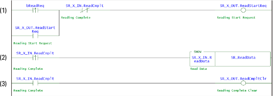
Flow of the above ladder program
- (1) bReadReq (Start reading) is turned ON to execute the read request.
- (2) When reading is complete, SR_X_IN.ReadDataCmplt (Reading complete) turns ON and the read string is stored starting from SR_ReadData (the read string).
- (3) At the same time, SR_X_OUT.ReadCmpltClr (Reading complete clear) is turned ON.
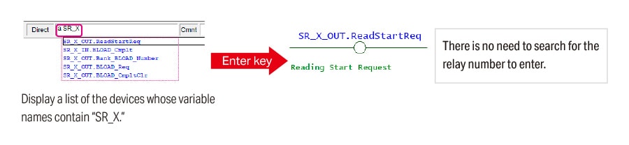
One point
Ladder creation from variable name
When entering operands, you can use the RT (Real-Time) Edit function to enter variables just by entering a part of the variable name. This function eliminates the hassle of searching for the variable name, which reduces the amount of man-hours spent programming.
Data handshake: Disabled
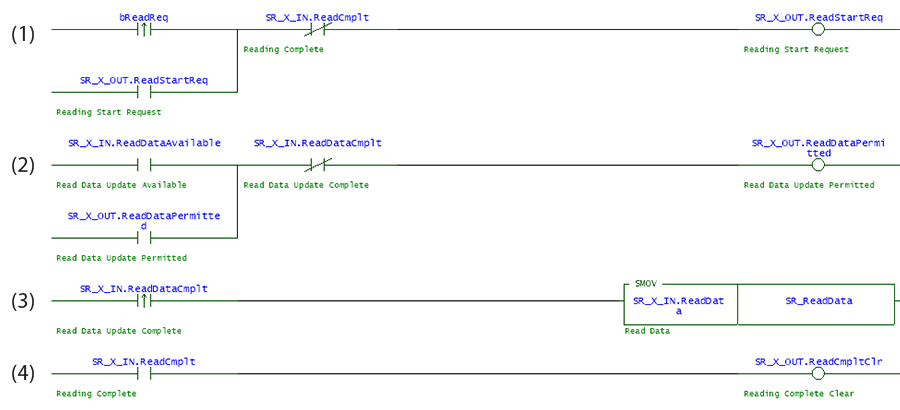
Flow of the above ladder program
- (1) The Reading request relay (SR_X_OUT.ReadStartReq) is turned ON to execute the read request. When the Reading complete relay (SR_X_IN.ReadDataCmplt) turns ON, the Reading request relay (SR_X_OUT. ReadStartReq) is turned OFF.
- (2) When the Data update possible relay (SR_X_IN.ReadDataAvailable) turns ON, the Data update permitted relay (SR_X_OUT.ReadDataPermitted) is turned ON.
- (3) When the Data update complete relay (SR_X_IN.ReadDataCmplt) turns ON, the read string is stored starting from SR_ReadData.
- (4) When the Reading complete relay (SR_X_IN.ReadDataCmplt) turns ON, the Reading complete clear relay (SR_X_OUT.ReadCmpltClr) is turned ON.
One point
When the Reading complete clear relay turns ON, the matching level (SR_X_IN.MatchLevel) is also cleared to zero.
Storing the value of the matching level in a different device before turning ON the Reading complete clear relay makes it possible to check the matching level even after clearing the reading completion.
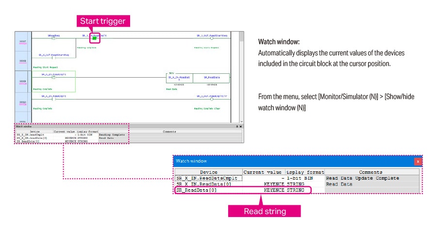
< Operation check >
Check the operation of the reference program with the following procedure.
1. Turn ON bReadReq (Start reading).
2. The code reader starts scanning. Read one of the following 2D codes (code type: QR).

3. When reading is complete, the read string is stored starting from SR_ReadData.
4. Check whether the string stored starting from SR_ReadData matches the data details of the 2D code.
Reference 3 : Ladder Program Example - BLOAD -
In this program example, the following SR-X Series device assignments are used to switch to the settings of file number 1.
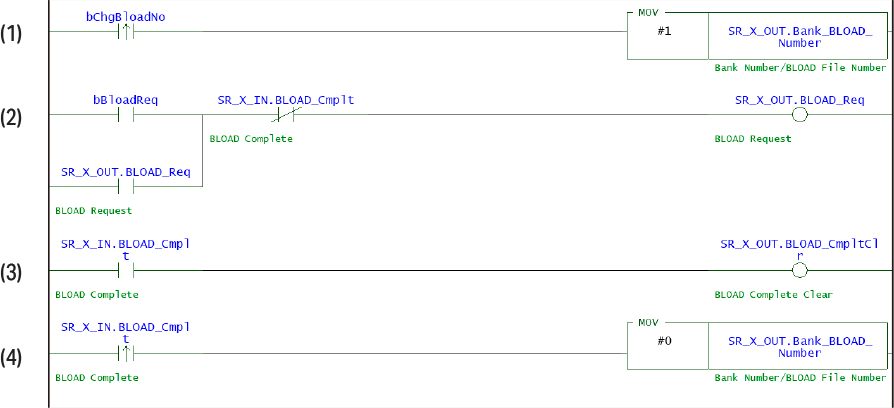
Flow of the above ladder program
- (1) 1 is stored in the BLOAD number (SR_X_OUT.Bank_BLOAD_Number).
- (2) The BLOAD request relay (SR_X_OUT.BLOAD_Req) is turned ON to execute the BLOAD change. When the BLOAD complete relay (SR_X_IN.BLOAD_Cmplt) turns ON, the BLOAD request relay (SR_X_OUT.BLOAD_Req) is turned OFF.
- (3) When the BLOAD complete relay (SR_X_IN.BLOAD_Cmplt) turns ON, the BLOAD complete clear relay (SR_X_OUT.BLOAD_CmpltClr) is turned ON.
- (3) When the BLOAD complete relay (SR_X_IN.BLOAD_Cmplt) turns ON, 0 is stored in the BLOAD number (SR_X_OUT.Bank_BLOAD_Number).
-
*The bank number and BLOAD number use a common address, so the value is reset to 0 after use.
Reference 4 : Ladder Program Example - Bank-specified Reading -
In this program example, the following SR-X Series device assignments are used, the code reader is instructed to start reading with the settings of bank number 1, and the read string is stored in SR_ReadData.
Data handshake: Disabled
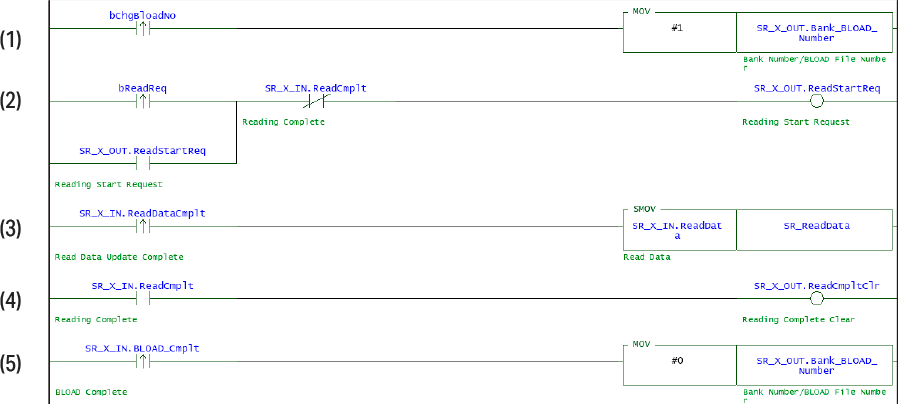
Flow of the above ladder program
- (1) 1 is stored in the Bank number (SR_X_OUT.Bank_BLOAD_Number).
- (2) The Reading request relay (SR_X_OUT.ReadStartReq) is turned ON to execute the read request. When the Reading complete relay (SR_X_IN.ReadDataCmplt) turns ON, the Reading request relay (SR_X_OUT.ReadStartReq) is turned OFF.
- (3) When the Reading complete relay (SR_X_IN.ReadDataCmplt) turns ON, the read string is stored starting from SR_ReadData.
- (4) When the Reading complete relay (SR_X_IN.ReadDataCmplt) turns ON, the Reading complete clear relay (SR_X_OUT.ReadCmpltClr) is turned ON.
- (5) When the Reading complete relay (SR_X_IN.ReadDataCmplt) turns ON, 0 is stored in the Bank number (SR_X_OUT.Bank_BLOAD_Number).
- *The bank number and BLOAD number use a common address, so the value is reset to 0 after use.
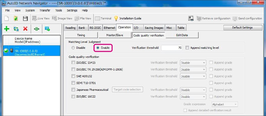
Extra 1 : Matching Level Reading
The matching level is a reference value used to judge how easy it was for the SR-X/SR-2000/1000/750/700/D100 Series code reader to successfully read a code. Matching level data is stored in the cyclic communication area, so the matching level can be checked without a ladder program.
Enable the matching level judgment function.
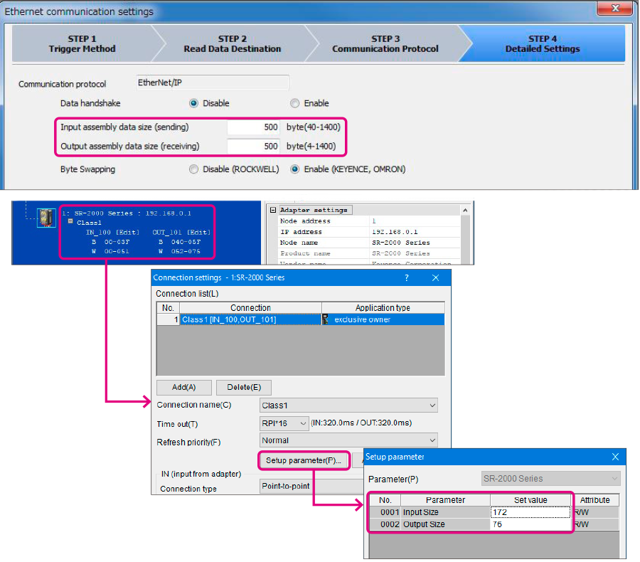
Extra 2 : Changing the Cyclic Data Size
You can change the size of the data transferred in cyclic communication (the initial value for the maximum number of bytes of the number of read digits in cyclic communication is 126) when the size of the data transferred to the KV Series is too large due to too many digits being read by the SR-X/SR Series.
- *Communication is possible when the Input assembly data size (sending) and Output assembly data size (receiving) of the SR-X/SR Series are larger than, respectively, the Input Size and Output Size of the KV Series.
SR-X Series setting method