KV-X Series × NQ Series
EtherNet/IP™ Connection Guide
Return to KV Series Connection Guide
KV-X Series × NQ Series EtherNet/IP™ Connection Guide
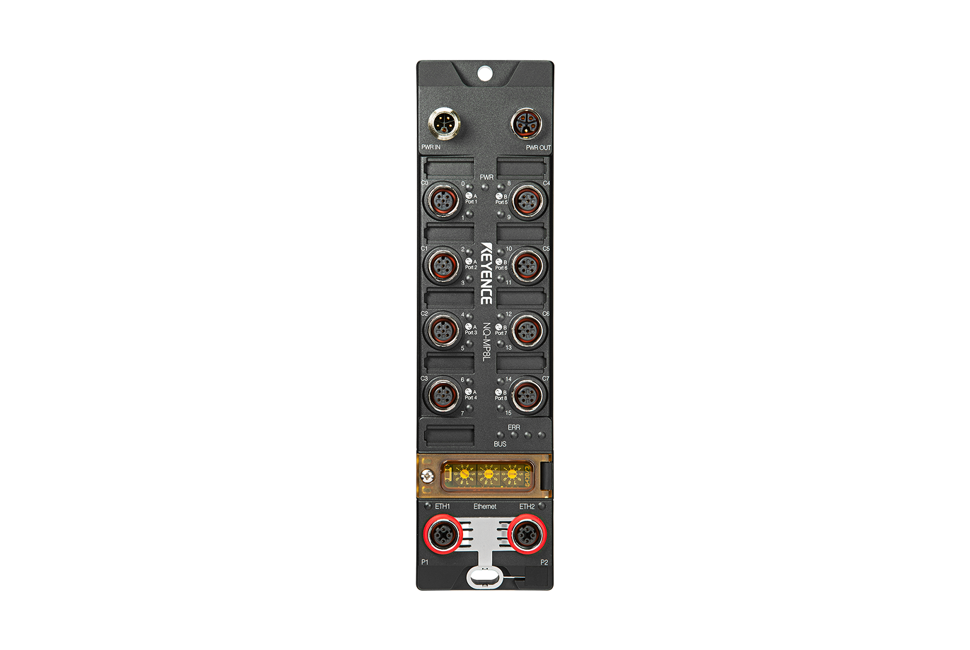
NQ Series

Contents
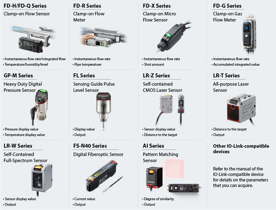
Preface : Sensors That Can Be Connected to the NQ Series
The NQ Series of IO-Link master modules supports EtherNet/IP and other main industrial Ethernet protocols.
The IO-Link devices that you can connect to the NQ Series and typical examples of the parameters that you can acquire are shown below.
* The parameters that you can acquire vary depending on the process data format.
Step 1 : Equipment Required for Connection
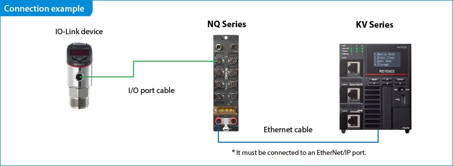
This section explains an example of using the NQ Series to connect the KV Series and the GP-M Series. As necessary, replace references to these devices with the devices to be used.
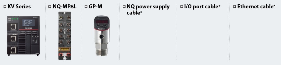
* The cable to use varies depending on the cable length and connector shape. Refer to the NQ Series manual and prepare the required cable.

One point
The NQ Series has two Ethernet ports, so you can connect multiple NQ Series units to one KV Series by wiring them as shown below.
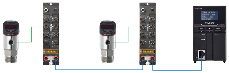
* The actual number of NQ Series units that can be connected depends on the types and current consumption of the IO-Link devices to connect to the NQ Series.
Refer to the NQ Series User’s Manual for details.
Step 2 : NQ Series Settings
This document explains the example of the case in which the following IP addresses are assigned to the NQ Series and the PC. Connect the PC and the NQ Series with an Ethernet cable before carrying out the following procedure.
NQ Series …… 192.168.0.1
PC …… 192.168.0.100 (Set the PC IP address in advance.)
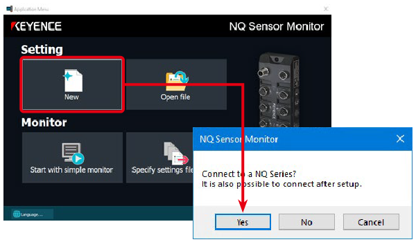
1. Start NQ Sensor Monitor and click [New]. A dialog box confirming that you want to connect to the NQ Series is displayed. Click [Yes].
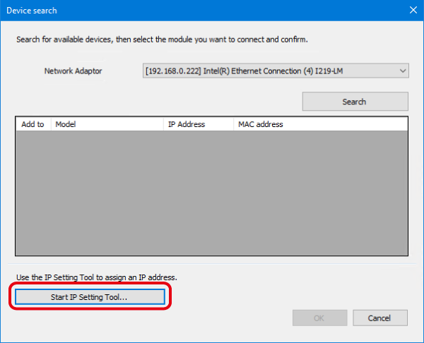
2. The [Device search] dialog box appears. Click [Start IP Setting Tool].
* If IP Setting Tool is not installed on the PC, this tool’s installer will be displayed the first time you start it. Follow the instructions of the installer to install IP Setting Tool.
* If an IP address has already been set on the NQ Series, go to step 6 without starting IP Setting Tool.
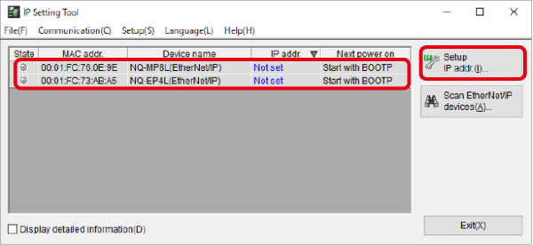
3. IP Setting Tool starts. Select the NQ Series whose IP address has not been set and click [Setup IP address (I)].
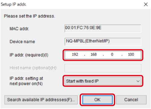
4. In the [Setup IP address] dialog box, configure the settings as shown below and click [OK].
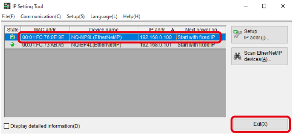
5. Check that the IP address setting has been applied, and then click [Exit (X)].
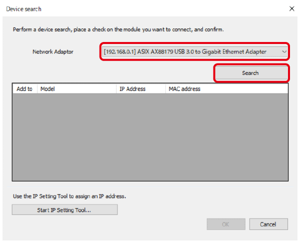
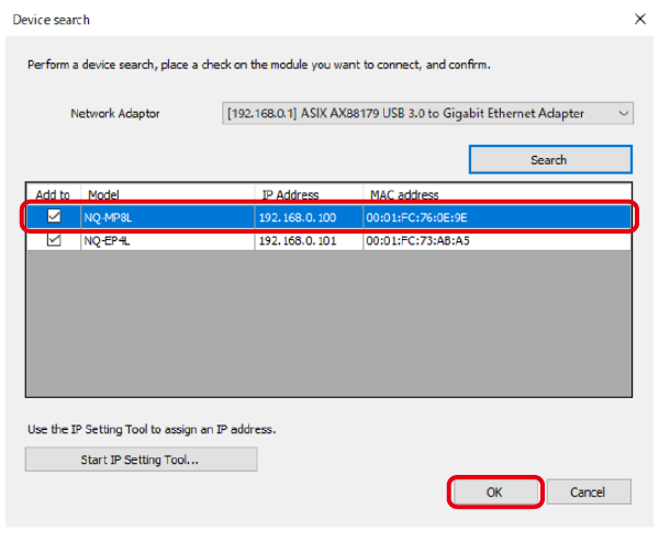
6. In the [Device search] dialog box, use the Network adapter list to select the adapter connected to the NQ Series, and then click [Search].
7. The NQ Series unit to which the IP address is assigned is displayed. Select this unit and click [OK].
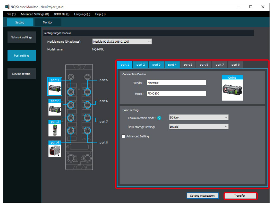
8. Click [Port setting] and check that the information of the sensor connected to the NQ Series has been applied correctly.
If there are no problems with the settings, click [Transfer] to transfer the setting details to the NQ Series.
This completes the setup of the NQ Series network. Configure other settings as necessary. Refer to the NQ Series User’s Manual for setting details.
Step 3 : KV-X Series Connection Settings
This section explains how to connect with a fictitious device called "Vendor Series". Replace the "Vender Series" with the device to be connected.
One point
For the KV Series with a CPU function version of 2.0 or later, variables can be assigned to the connection of EtherNet/IP.
When assigning variables to the connection of EtherNet/IP®, check the box of “Displays the variable setting dialog when updating the EtherNet/IP settings (E)” for “Other settings” of “System settings” on the “CPU system settings” dialog.
The “CPU system settings” dialog is displayed by selecting [Display (V)] ⇒ [CPU system settings (P)] from the ”KV STUDIO” menu.
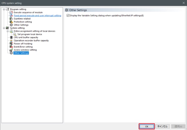
When the box of "Displays the variable setting dialog when updating the EtherNet/IP settings (E)" is checked, at the timing when the EtherNet/IP setting is updated and the changed content of the unit editor is confirmed, a dialog to assign variables to the connection is displayed.
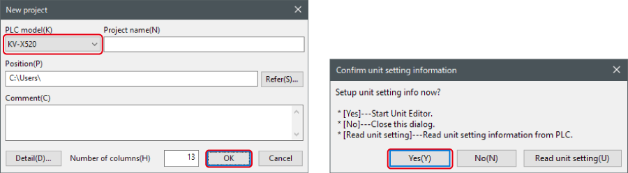
1. Start up the KV STUDIO and create a new project. Set the model option to “KV-X520” and click [OK].
A [Confirm unit configuration setting] dialog box is displayed. Click [Yes (Y)].
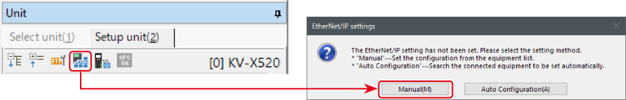
2. The unit editor is displayed. On the “Setup unit(2)” tab, click the icon of EtherNet/IP setting. A configuration type selection dialog box is displayed. Click [Manual (M)].
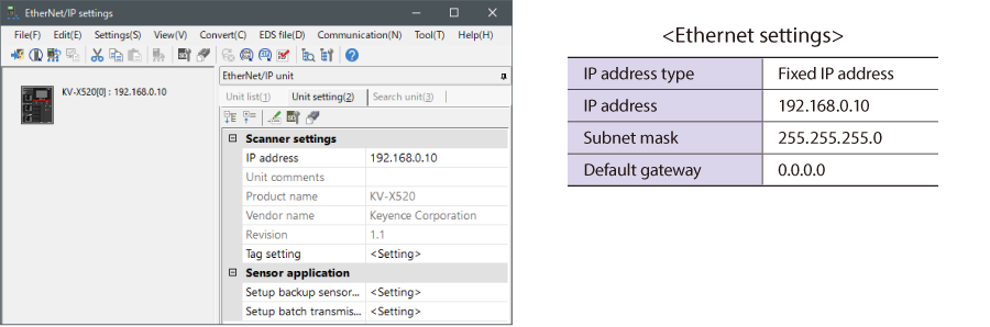
3. On the “Unit setting (2)” tab, set the IP address for KV-X Series. In this example, configure the setting as shown below.
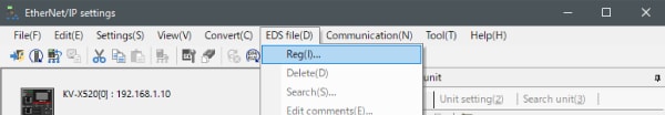
* Step 4 needs to be performed to import a sensor setting file. When the sensor setting file has already been imported, proceed to Step 5.
4. Select [EDS file (D)] → [Reg (I)] to import the KEYENCE sensor setting file(ez1 file) or EDS file.
* Download the sensor setting file from the KEYENCE website.
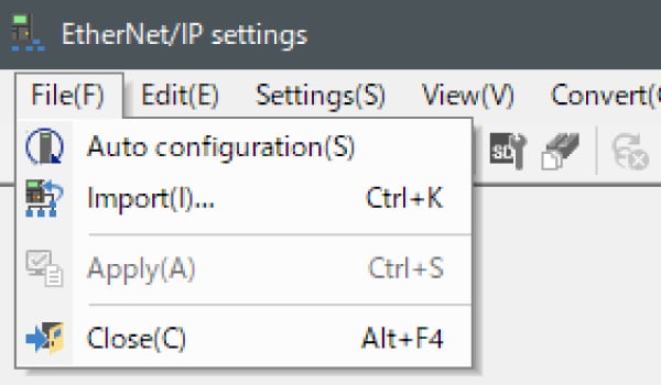
5. With the KV-X Series and the EtherNet/IP devices connected using the Ethernet cable, select [File (F)] → [Auto configuration (S)] on the [EtherNet/IP settings] window.
6. When the configuration on the unit editor differs from that of the actual device, a dialog for confirming transfer of the project is displayed. With the PC and KV-X Series connected using the USB cable, click [Yes (Y)].
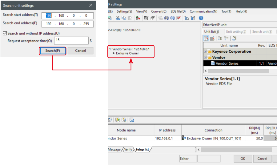
7. When transfer of the project is completed, the [Search unit settings] dialog is displayed. Then click [Search (F)]. After the auto configuration is completed, "Vendor Series" is automatically registered. Then click [OK] to close the [EtherNet/IP settings] window.
8. Click [OK] on the unit editor to exit.
One point
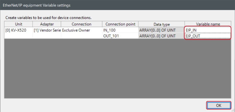
When the box of "Displays the variable setting dialog when updating the EtherNet/IP settings (E)" is checked, the [EtherNet/IP equipment Variable settings] dialog is displayed.
Enter the name of variable assigned to the connection, and click [OK].
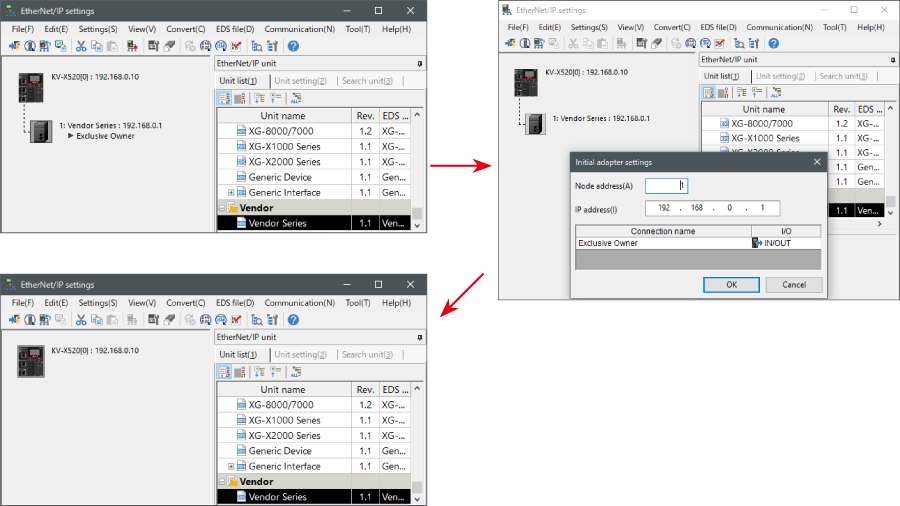
- The way of Device Configuration Settings manually
In the [Unit list (1)] tab of “EtherNet/IP Settings”, drag and drop "Vendor Series" and create a device configuration.
Transferring and Monitoring Setting Data
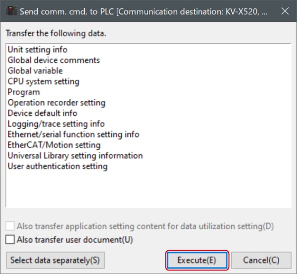
1. From the menu, select [Monitor/Simulator (N)] > [Transfer to PLC (W) → Monitor mode (C)].
In the [Send comm. cmd. to PLC] dialog box, click [Execute(E)].
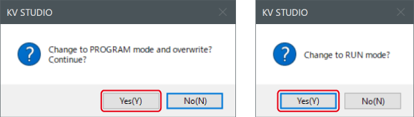
2. If the following dialog box is displayed before and after transferring the data, click [Yes] both times.
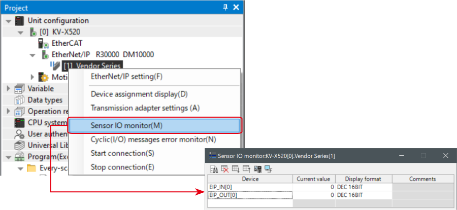
3. Right-click on “Vender Series” in the workspace, and select [Sensor IO monitor (M)].
Scores and other information can be easily monitored.
One point
The information can also be checked on a graph by starting up the real time chart monitor.
Right-click on “Sensor I/O monitor” and select [Real time chart monitor (H)].
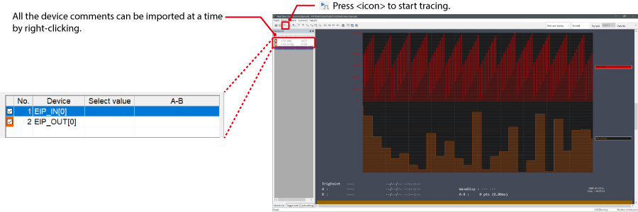
Range adjustment is not required since the real time chart monitor performs scaling automatically.
When Manipulating Parameters with a Program
Changing the Setting Values
The setting values of the sensors can be changed by the following two methods:
A : Change from a PC
B : Change from a ladder program
A : Change from a PC
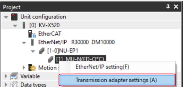
To change the settings from a PC, use the transmission adapter function in KV STUDIO.
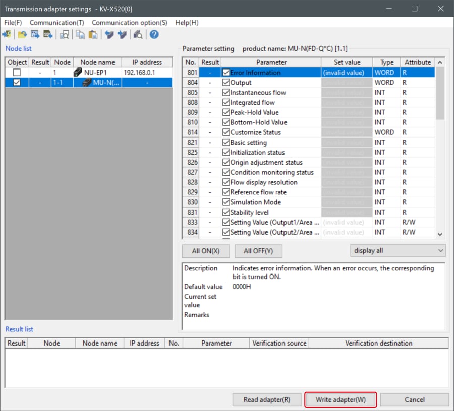
1. Expand the unit configuration in the workspace. Right-click on "Vender Series" and select [Transmission adapter settings (A)].
2. Place a check mark in Setting Value for "Vender Series" and enter the setting value.
Click [Write adapter (W)] to write the setting value to the sensor.
*To read the setting value of a sensor, select [Read adapter (R)].
B : Changed from a ladder program
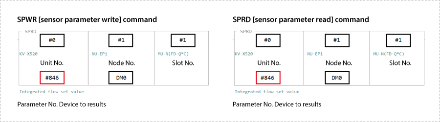
Use message communication to change the setting values from a ladder program.
To perform message communication with KV STUDIO, use the sensor setting commands (SPWR [sensor parameter write] and SPRD [sensor parameter read]).
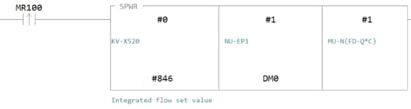
1. In Editor mode, create a ladder program as shown below.
* For the parameter numbers, refer to Parameter list.
2. Transfer the ladder program.
3. When MR100 is turned on, the setting value is changed.
* Store the setting value in DM4 ([Leading device to store results] + 4).
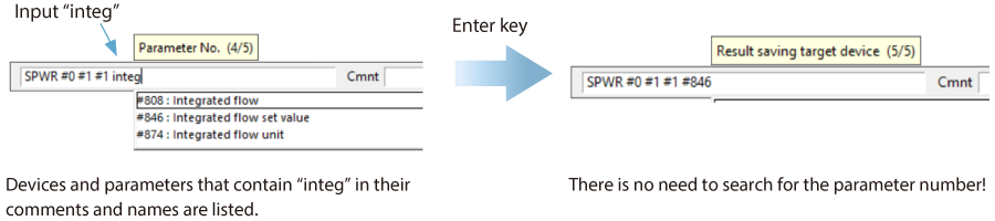
One point
RT (Real-Time) Edit function
When you use a ladder program, you can input device comments or parameter names directly to have input candidates be searched for and displayed automatically.