KV-X Series × MP-F Series
EtherNet/IP™ Connection Guide
Return to KV Series Connection Guide
KV-X Series × MP-F Series EtherNet/IP™ Connection Guide
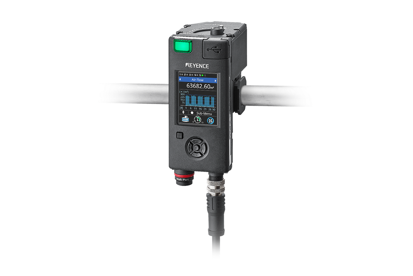
MP-F Series

Contents
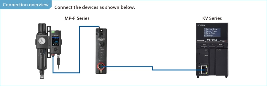
Step 1 : Devices required for connection
MP-F Series
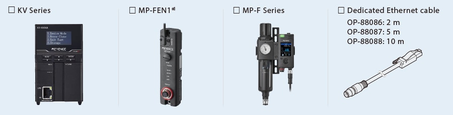
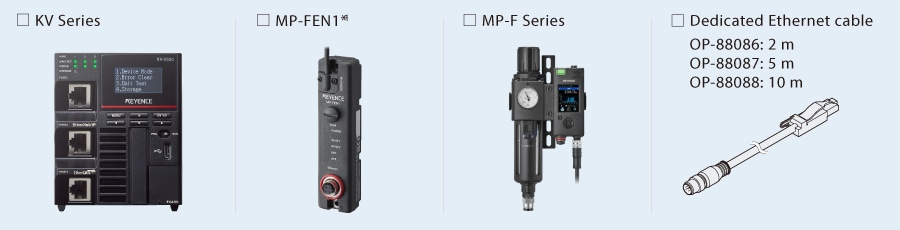
※1 One Ethernet module (MP-FEN1) is required for one unit of MP-F Series.
Step 2 : EtherNet/IP setup for MP-F Series
EtherNet/IP setup for the MP-F Series is configured for MP-FEN1.
The following MP-FEN1 setup methods are available.
(1) Setup from KV STUDIO (*This setup is possible only when the MP-FEN1 is in the default state.)
(2) Setup from the MP-F Series
(3) Setup from the MP-F Monitor, which is MP-F Series software
Use setup method (2) or (3) in states other than the default state, and for the external input setting of the MP-F Series. (For method (3), refer to “One point”)
This manual describes the setup procedure from the KV STUDIO.
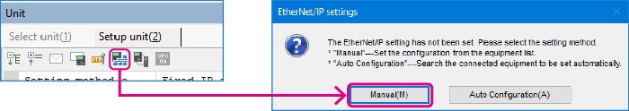
1. Open the Unit Editor of KV STUDIO, and click the EtherNet/IP settings icon. A configuration type selection dialog box is displayed. Click [Manual (M)].
*Step 2 is performed when a sensor configuration file needs to be imported. If a sensor configuration file has been already imported, connect KV Series and the sensor device via LAN cable, and click [Auto Configuration (A)] before proceeding to Step 3.
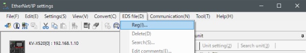
2. The [EtherNet/IP settings] window is displayed. Select [EDS file (D)] ⇒ [Reg (I)] to import the KEYENCE sensor configuration file for the MP-F Series (ez1 file).
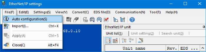
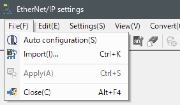
3. With KV Series and the sensor device connected via Ethernet cable, select [File (F)] ⇒ [Auto configuration (S)] on the [EtherNet/IP settings] window.
One point
This section describes the setup procedure on the MP-F Monitor.
- MP-FEN1 and KV Series are connected with LAN cable.
- Power is supplied to MP-FEN1 and KV Series.
- When an Ethernet switch is used, the Ethernet switch is connected to the MP-FEN1 and KV Series with LAN cable, and the power is supplied to the Ethernet switch.
4. When the configuration in the Unit Editor differs from that of the actual device, a dialog for confirming transfer of the project is displayed. With the PC and KV Series connected with USB cable, click [Yes (Y)].
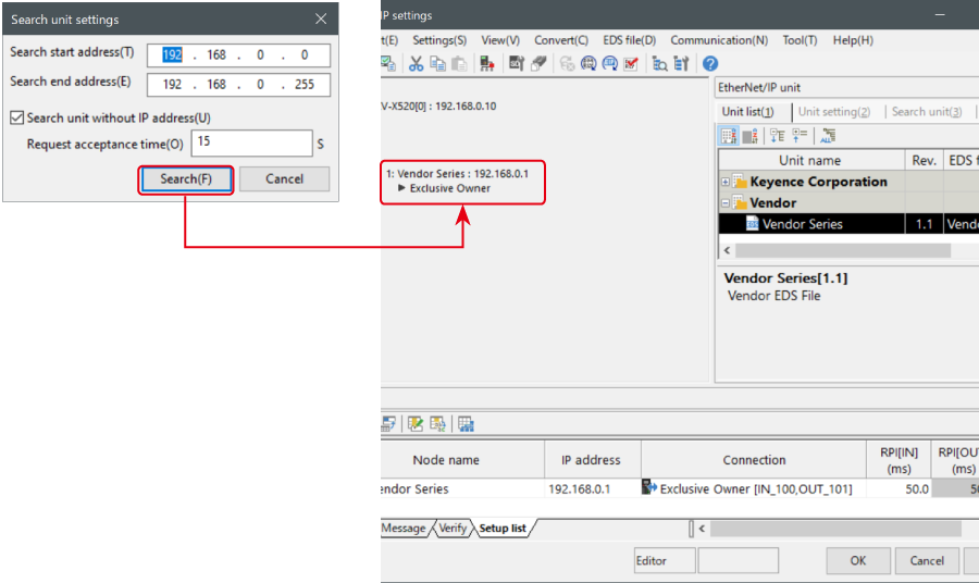
When the transfer of the project is completed, the [Search unit settings] dialog is displayed. Then click [Search (F)].
Select the unassigned MP-FEN1 from the search results, and click "Unassigned".
The [IP address setting] dialog box is displayed. Then, set the IP address of the MP-FEN1 to "192.168.0.1" and click [OK].
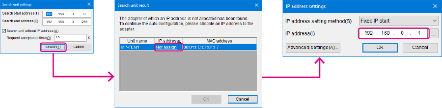
One point
Clicking  in the [IP address setting] dialog box allows IP addresses that have not been used to be searched for.
One point
This section describes the setup procedure on the MP-F Monitor.
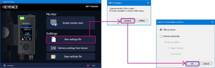
1. Connect the PC and MP-F Series using the USB cable (OP-51580: 2 m/OP-86941: 5 m), and connect the MP-F Series and
MP-FEN1 with the dedicated cable. Start the MP-F Monitor, and click [New] - [Connect].
The [Connection type selection] dialog box is displayed. Select "USB connection" and click [OK].
2. Click [Ethernet module] and configure the Ethernet settings of the MP-F Series.
Place a check in "Transfer communication setting" and configure the settings as shown below.
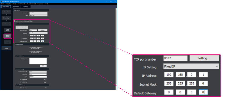
<Ethernet settings>
| TCP port number | 8637 |
|---|---|
| IP setting | Fixed IP |
| IP address | 192.168.0.1 |
| Subnet mask | 255.255.255.0 |
| Default gateway | 0.0.0.0 |
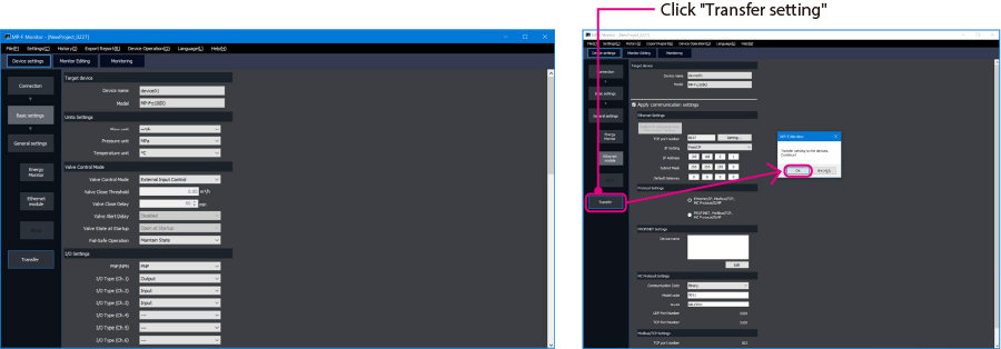
3. Select [Basic settings] and set "Valve control setting" to "External input control".
After the setting is complete, click [Transfer setting], and then click [OK] to transfer the setting contents to the MP-F Series.
*This setting is required to perform valve control from PLC.
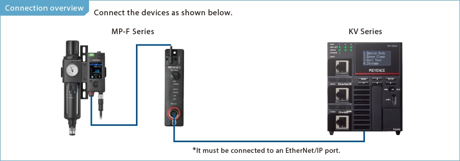
Step 3 : KV-X Series Connection Settings
This section explains how to connect with a fictitious device called "Vendor Series". Replace the "Vender Series" with the device to be connected.
One point
For the KV Series with a CPU function version of 2.0 or later, variables can be assigned to the connection of EtherNet/IP.
When assigning variables to the connection of EtherNet/IP®, check the box of “Displays the variable setting dialog when updating the EtherNet/IP settings (E)” for “Other settings” of “System settings” on the “CPU system settings” dialog.
The “CPU system settings” dialog is displayed by selecting [Display (V)] ⇒ [CPU system settings (P)] from the ”KV STUDIO” menu.
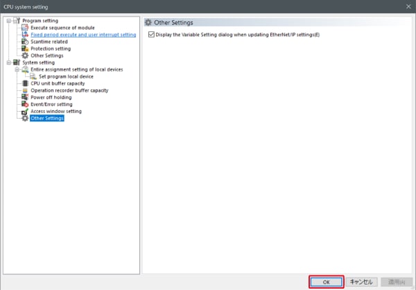
When the box of "Displays the variable setting dialog when updating the EtherNet/IP settings (E)" is checked, at the timing when the EtherNet/IP setting is updated and the changed content of the unit editor is confirmed, a dialog to assign variables to the connection is displayed.
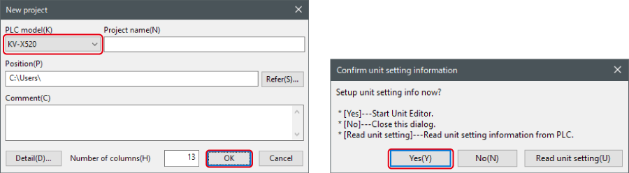
1. Start up the KV STUDIO and create a new project. Set the model option to “KV-X520” and click [OK].
A [Confirm unit configuration setting] dialog box is displayed. Click [Yes (Y)].
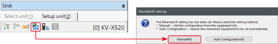
2. The unit editor is displayed. On the “Setup unit(2)” tab, click the icon of EtherNet/IP setting. A configuration type selection dialog box is displayed. Click [Manual (M)].
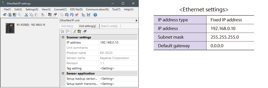
3. On the “Unit setting (2)” tab, set the IP address for KV-X Series. In this example, configure the setting as shown below.
* Step 4 needs to be performed to import a sensor setting file. When the sensor setting file has already been imported, proceed to Step 5.
4. Select [EDS file (D)] → [Reg (I)] to import the KEYENCE sensor setting file(ez1 file) or EDS file.
* Download the sensor setting file from the KEYENCE website.
5. With the KV-X Series and the EtherNet/IP devices connected using the Ethernet cable, select [File (F)] → [Auto configuration (S)] on the [EtherNet/IP settings] window.
6. When the configuration on the unit editor differs from that of the actual device, a dialog for confirming transfer of the project is displayed. With the PC and KV-X Series connected using the USB cable, click [Yes (Y)].
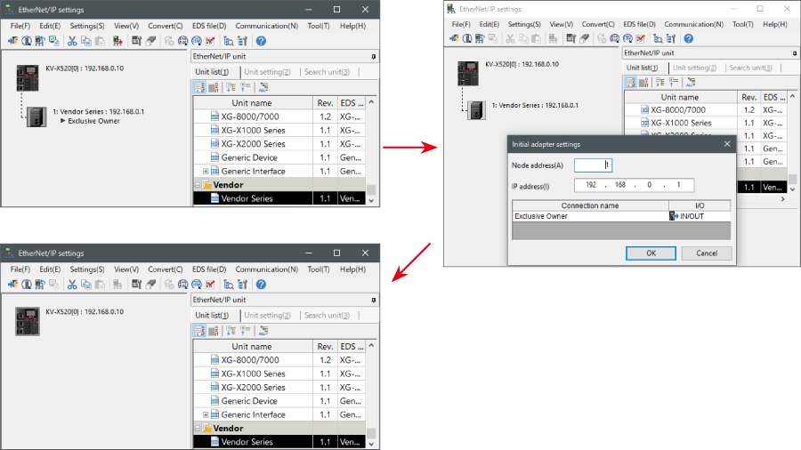
7. When transfer of the project is completed, the [Search unit settings] dialog is displayed. Then click [Search (F)]. After the auto configuration is completed, "Vendor Series" is automatically registered. Then click [OK] to close the [EtherNet/IP settings] window.
8. Click [OK] on the unit editor to exit.
One point
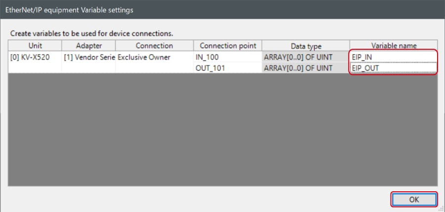
When the box of "Displays the variable setting dialog when updating the EtherNet/IP settings (E)" is checked, the [EtherNet/IP equipment Variable settings] dialog is displayed.
Enter the name of variable assigned to the connection, and click [OK].
- The way of Device Configuration Settings manually
In the [Unit list (1)] tab of “EtherNet/IP Settings”, drag and drop "Vendor Series" and create a device configuration.
Transferring and Monitoring Setting Data
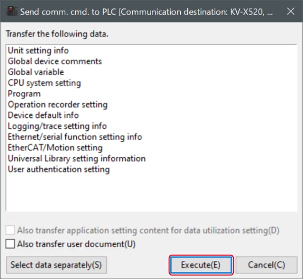
1. From the menu, select [Monitor/Simulator (N)] > [Transfer to PLC (W) → Monitor mode (C)].
In the [Send comm. cmd. to PLC] dialog box, click [Execute(E)].
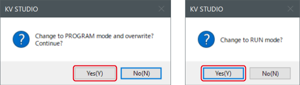
2. If the following dialog box is displayed before and after transferring the data, click [Yes] both times.
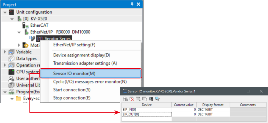
3. Right-click on “Vender Series” in the workspace, and select [Sensor IO monitor (M)].
Scores and other information can be easily monitored.
One point
The information can also be checked on a graph by starting up the real time chart monitor.
Right-click on “Sensor I/O monitor” and select [Real time chart monitor (H)].
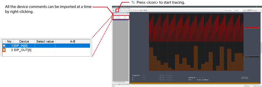
Range adjustment is not required since the real time chart monitor performs scaling automatically.
When Manipulating Parameters with a Program
Changing the Setting Values
The setting values of the sensors can be changed by the following two methods:
A : Change from a PC
B : Change from a ladder program
A : Change from a PC
To change the settings from a PC, use the transmission adapter function in KV STUDIO.
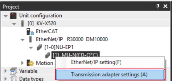
1. Expand the unit configuration in the workspace. Right-click on "Vender Series" and select [Transmission adapter settings (A)].
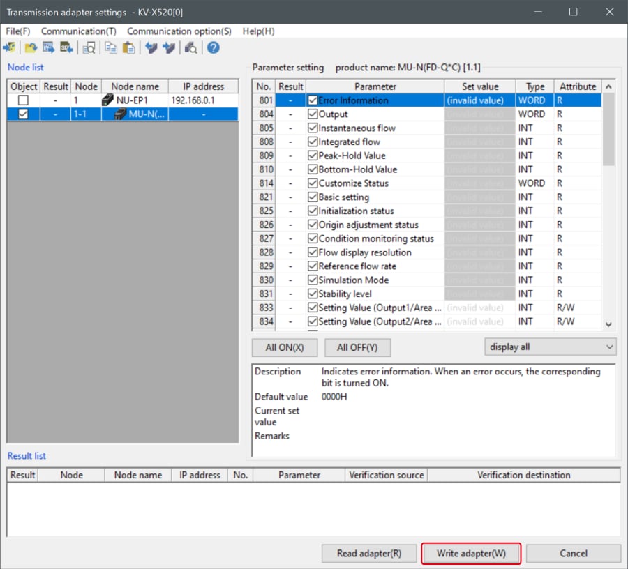
2. Place a check mark in Setting Value for "Vender Series" and enter the setting value.
Click [Write adapter (W)] to write the setting value to the sensor.
*To read the setting value of a sensor, select [Read adapter (R)].
B : Changed from a ladder program
Use message communication to change the setting values from a ladder program.
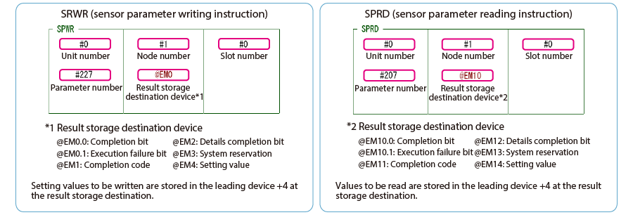
To perform message communication with KV STUDIO, use the sensor setting commands (SPWR [sensor parameter write] and SPRD [sensor parameter read]).
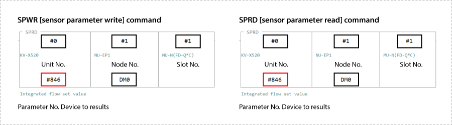
1. In Editor mode, create a ladder program as shown below.
* For the parameter numbers, refer to Parameter list.
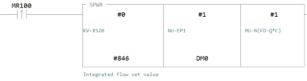
2. Transfer the ladder program.
3. When MR100 is turned on, the setting value is changed.
* Store the setting value in DM4 ([Leading device to store results] + 4).
One point
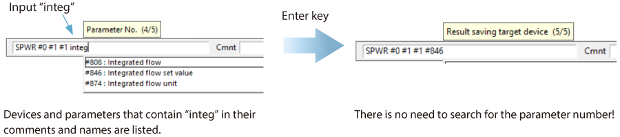
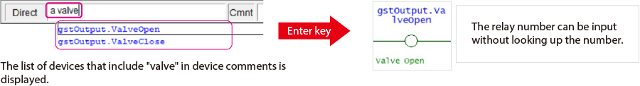
RT (Real-Time) Edit function
When you use a ladder program, you can input device comments or parameter names directly to have input candidates be searched for and displayed automatically.
Step 4 : Sample ladder to control the shut-off valve
OPEN/CLOSE control of the shut-off valve can be performed on the PLC. This section shows the sample ladder.
*The valve control settingof the MP-F Series needsto be set to "External input control". (See One Point)
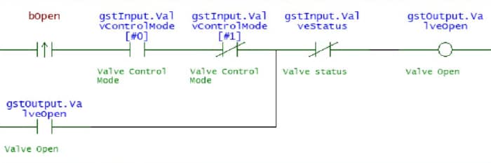
1. Put KV STUDIO in Editor Mode. On the Ladder Program, create ladders to control the shut-off valve. With the control setting set to "External input control", this program requests until the valve status is changed.
Valve OPEN Request
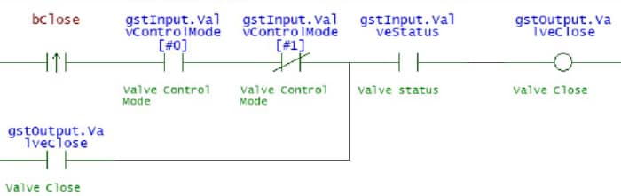
Valve CLOSE Request
Mnemonicsymbol list
LDP bOpen
AND gstInput.ValvControlMode[#0] ANB gstInput.ValvControlMode[#1] OR gstOutput.ValveOpen
ANB gstInput.ValveStatus OUT gstOutput.ValveOpen
LDP bClose
AND gstInput.ValvControlMode[#0] ANB gstInput.ValvControlMode[#1] OR gstOutput.ValveClose
AND gstInput.ValveStatus OUT gstOutput.ValveClose
2. Transfer the created program to the PLC.
Select [Monitor/simulator (N)] ⇒ [Transfer to PLC ⇒ Monitor mode (C)] ⇒ [Transfer with PROGRAM Mode (P)], and click [Execute].
3. Set PLC to "RUN".
4. To OPEN using the above program in <KV STUDIO> monitor, set "bOpen" to ON, and to CLOSE, set "bClose" to ON to control the shut-off valve.
One point
⇒ No manual required to create ladders!
A relay number can be input only by entering a partial device comment during operand input. (RT edit function)
Eliminating time to look up relay numbers reduces man-hours to create a program.
Extra : Memory mapping
MP-F Series [EtherNet/IP] setting
The following is the list of parameters that can be exchanged in cyclic communication and message communication.
▶ List of parameters that can be obtained in cyclic communication
Since the parameters that can be obtained in cyclic communication are automatically updated between the KV Series and MP-F Series at a fixed internal, a program for reading and writing data is not required. The following is a device map where B000 and W000 are assigned to the leading device of the MP-F Series link devices.
MP-F Series → KV Series
| Member Name | Data Type | Detail |
|---|---|---|
| Ch1_Output | BOOL | Ch.1 Output |
| Ch2_Output | BOOL | Ch.2 Output |
| Ch3_Output | BOOL | Ch.3 Output |
| Ch4_Output | BOOL | Ch.4 Output |
| Ch5_Output | BOOL | Ch.5 Output |
| Ch2_Input | BOOL | Ch.2 Input |
| Ch3_Input | BOOL | Ch.3 Input |
| Ch6_Input | BOOL | Ch.6 Input |
| ZeroFlow | BOOL | Zero flow |
| ValveStatus | BOOL | Valve status |
| ValveControlReq | BOOL | Valve Control Request |
| ValvControlMode | ARRAY[0..1] OF BOOL | Valve Control Mode |
| CycleStatus | BOOL | Cycle status |
| FlowMeasurement | BOOL | Flow measurement |
| PressureMeasurement | BOOL | Pressure measurement |
| TempMeasurement | BOOL |
Temperature measurement |
| HumidityMeasurement | BOOL | Humidity measurement |
| DewPointMeasurement | BOOL |
Dew point measurement |
| DetectableStatus | BOOL | Detectable Status |
| HistoryDataReady | BOOL | History data ready |
| InstantFlow | UINT | Instant.Flow |
| InstantFlow_Peak | UINT | Instant.Flow_Peak |
| InstantFlow_Bottom | UINT | Instant.Flow_Bottom |
| LeakageFlowRate | UINT | Leakage flow rate |
| SavedLeakFlowRate | UINT | Saved leak flow rate |
| AccumulatedFlow | UDINT | Accumulated Flow |
| Pressure | INT | Pressure |
| Pressure_Peak | INT | Pressure_Peak |
| Pressure_Bottom | INT | Pressure_Bottom |
| Temperature | INT | Temperature |
| DewPoint | INT | Dew point |
| Humidity | UINT | Humidity |
| ActivePower | DINT | Reactive Power |
| ApparentPower | DINT | Apparent Power |
| AccumActEnergy | UDINT | Accum. Act.Energy |
| AccumAppEnergy | UDINT | Accum. App.Energy |
| AccumFlow_Cycle | UDINT | Accum. Flow/Cycle |
| ElecEnergy_Cycle | UDINT | Elec. Energy/Cycle |
| CycleTime | UDINT | Cycle Time |
| FlowCycle_Today | UDINT | Flow/Cycle (Today) |
| EnergyCycle_Today | UDINT | Energy/Cycle(Today) |
| CycleTime_Today | UDINT | Cycle time (Today) |
| CycleCount_Today | UDINT | Cycle count (Today) |
| ElapsedTime_Today | UDINT | Elapsed Time(Today) |
| OperatTime_Today | UDINT | Operat. Time(Today) |
| Year | UINT | Year |
| Month | UINT | Month |
| Day | UINT | Day |
| Hour | UINT | Hour |
| Minute | UINT | Minute |
| sec | UINT | sec |
| ErrorInformation | UINT | Error Information |
| Reso_InstantFlow | UINT | Reso_Instant.Flow |
| Reso_Pressure | UINT | Reso_Pressure |
| Reso_Temperature | UINT | Reso_Temperature |
| Reso_Humidity | UINT | Reso_Humidity |
| Reso_DewPoint | UINT | Reso_Dew point |
| Reso_AccumFlow | UINT | Reso_Accum. Flow |
| Reso_ElecPower | UINT | Reso_Elec. Power |
| Reso_ElecEnergy | UINT | Reso_Elec. Energy |
KVSeries → MP-F Series
| Member Name | Data Type | Detail |
|---|---|---|
| AccumFlowReset | BOOL | Accum. flow reset |
| ZeroFlow | BOOL | Zero flow |
| ValveOpen | BOOL | Valve Open |
| ValveClose | BOOL | Valve Close |
| CycleStart | BOOL | Cycle Start |
| CycleStop | BOOL | Cycle Stop |
| AccumEnergyReset | BOOL | Accum. energy reset |
| HoldReset | BOOL | Hold reset |
| Reserved |
ARRAY[0..15] OF BOOL |
▶ List of parameters that can be obtained in message communication
The message communication is a communication method used when data is exchanged at an arbitrary timing such as change of setting values. The message communication requires a ladder program for communication. However, the KV Series enables communication only by using dedicated instruction words (SPWR/SPRD instruction) for communicating with KEYENCE sensors.
| Attribute ID | Parameter No. | Item |
|---|---|---|
| 500 | 500 | Model |
| 501 | 501 | Ethernet module Connection |
| 502 | 502 | Energy Monitor 0 Connection |
| ~ | ~ | ~ |
| 511 | 511 | Energy Monitor 9 Connection |
| 512 | 512 | IO-Link serial number |
| 514 | 514 | IO-Link serial number |
| 516 | 516 | IO-Link serial number |
| 518 | 518 | IO-Link serial number |
| 520 | 520 | I/O Status |
| 521 | 521 | Device Status |
| 522 | 522 | Error Information 1 |
| 524 | 524 | Error Information 2 |
| 526 | 526 | Error Information 3 |
| 600 | 600 | Command Execution |
| 601 | 601 | Command Statuses |
| 1000 | 1000 | PNP/NPN |
| 1001 | 1001 | Ch.1 I/O Type |
| 1002 | 1002 | Ch.1 Target |
| 1003 | 1003 | Ch.1 Logic |
| 1004 | 1004 | Ch.1 Detection Mode |
| 1005 | - | Reserved for System |
| 1006 | 1006 | Ch.1 Low Threshold |
| 1008 | 1008 | Ch.1 High Threshold |
| 1030 | 1030 | Ch.1 Analog Target |
| 1031 | - | Reserved for System |
| 1032 | 1032 | Ch.1 Analog Lower Limit |
| 1034 | 1034 | Ch.1 Analog Upper Limit |
| 1100 | - | Reserved for System |
| 1101-1200 | - | (Ch.2) |
| 1201-1300 | - | (Ch.3) |
| 1301-1400 | - | (Ch.4) |
| 1401-1500 | - | (Ch.5) |
| 1501-1600 | - | (Ch.6) |
| 2000 | 2000 | Instant.Flow |
| 2001 | 2001 | Instant.Flow_Peak |
| 2002 | 2002 | Instant.Flow_Bottom |
| 2003 | - | Reserved for System |
| 2004 | 2004 | Accumulated Flow |
| 2006 | 2006 | Leakage flow rate |
| 2007 | 2007 | Saved leak flow rate |
| 2008 | 2008 | Reso_Instant.Flow |
| 2009 | 2009 | Reso_Accumulated Flow |
| 2020 | 2020 | Pressure_ Current value |
| 2021 | 2021 | Pressure_Peak |
| 2022 | 2022 | Pressure_Bottom |
| 2023 | 2023 | Reso_Pressure |
| 2030 | 2030 | Temperature _ Current value |
| 2031 | 2031 | Dew point _ Current value |
| 2032 | 2032 | Humidity _ Current value |
| 2033 | 2033 | Dew point_Enabled |
| 2034 | 2034 | Humidity_Enabled |
| 2035 | 2035 | Reso_Temperature |
| 2036 | 2036 | Reso_Dew point |
| 2037 | 2037 | Reso_Humidity |
| 2040 | 2040 | Valve status Monitor |
| 2041 | 2041 | Valve Control Request Status |
| 2042 | 2042 | Valve Operation Method |
| 2043 | 2043 | Valve Thres. Calibration Status |
| 2044 | 2044 | Valve Close Threshold |
| 2045 | - | Reserved for System |
| 2050 | 2050 | Total Active Power |
| 2052 | 2052 | Reserved for System |
| 2054 | 2054 | Total Apparent Power |
| 2056 | 2056 | Total Accum. Act.Energy |
| 2058 | 2058 | Reserved for System |
| 2060 | 2060 | Total Accum. App.Energy |
| 2062 | 2062 | Common(Energy)_System A Address |
| ~ | ~ | ~ |
| 2071 | 2071 | Common(Energy)_System J Address |
| 2072 | 2072 | Reso_Phase Voltage |
| 2073 | 2073 | Reso_Line Voltage |
| 2074 | 2074 | Reso_Current |
| 2075 | 2075 | Reso_Active Power |
| 2076 | 2076 | Reso_Reactive Power |
| 2077 | 2077 | Reso_Apparent Power |
| 2078 | 2078 | Reso_Accum. Act.Energy |
| 2079 | 2079 | Reso_Accum. Rct.Energy |
| 2080 | 2080 | Reso_Accum. App.Energy |
| 2081 | 2081 | Reso_Frequency |
| 2082 | 2082 | Reso_Power Factor |
| 2100 | - | A_Phase Voltage_1 |
| 2101 | - | A_Phase Voltage_2 |
| 2102 | - | A_Phase Voltage_3 |
| 2103 | - | A_Phase Voltage_(Average) |
| 2104 | - | A_Line Voltage_1 |
| 2105 | - | A_Line Voltage_2 |
| 2106 | - | A_Line Voltage_3 |
| 2107 | - | A_Line Voltage_(Average) |
| 2108 | - | A_Current_1 |
| 2110 | - | A_Current_2 |
| 2112 | - | A_Current_3 |
| 2114 | - | A_Current_(Average) |
| 2116 | - | A_Active Power_1 |
| 2118 | - | A_Active Power_2 |
| 2120 | - | A_Active Power_3 |
| 2122 | - | A_Active Power_(Total) |
| 2124 | - | A_Reactive Power_1 |
| 2126 | - | A_Reactive Power_2 |
| 2128 | - | A_Reactive Power_3 |
| 2130 | - | A_Reactive Power_(Total) |
| 2132 | - | A_Apparent Power_1 |
| 2134 | - | A_Apparent Power_2 |
| 2136 | - | A_Apparent Power_3 |
| 2138 | - | A_Apparent Power_(Total) |
| 2140 | - | A_Accum. Act.Energy |
| 2142 | - | A_Accum. Rct.Energy |
| 2144 | - | A_Accum. App.Energy |
| 2146 | - | A_Frequency |
| 2147 | - | A_Power Factor |
| 2150-2197 | - | (B_***) |
| 2200-2247 | - | (C_***) |
| 2250-2297 | - | (D_***) |
| 2300-2347 | - | (E_***) |
| 2350-2397 | - | (F_***) |
| 2400-2447 | - | (G_***) |
| 2450-2497 | - | (H_***) |
| 2500-2547 | - | (I_***) |
| 2550-2597 | - | (J_***) |
| 2800 | 2800 | Simulation Mode |
| 2801 | 2801 | Output Ch.1 Simulation |
| 2802 | 2802 | Analog Ch.1 Simulation |
| 2803 | 2803 | Output Ch.2 Simulation |
| 2804 | 2804 | Analog Ch.2 Simulation |
| 2805 | 2805 | Output Ch.3 Simulation |
| 2806 | 2806 | Output Ch.4 Simulation |
| 2807 | 2807 | Output Ch.5 Simulation |
| 2808 | 2808 | Flow Simulation |
| 2809 | 2809 | Pressure Simulation |
| 2810 | 2810 | Temperature Simulation |
| 2811 | 2811 | Humidity Simulation |
| 2812 | 2812 | Dew point Simulation |
| 2813 | - | Reserved for System |
| 2814 | 2814 | Total Active Power Simulation |
| 2816 | 2816 | Error Simulation |
| 2817 | - | Reserved for System |
| 3000 | 3000 | Averaging time (Flow) |
| 3001 | - | Reserved for System |
| 3002 | - | Reserved for System |
| 3003 | 3003 | Display Averaging (Flow) |
| 3004 | 3004 | Hysteresis (Flow) |
| 3005 | 3005 | Zero Cut Flow Rate |
| 3006 | 3006 | Flow Pulse Weight |
| 3008 | 3008 | Accumulated Flow Auto reset |
| 3009 | 3009 | Span Adjustment |
| 3010 | 3010 | Advanced Detection Settings |
| 3011 | 3011 | Reference Temperature |
| 3012 | 3012 | Flow unit |
| 3013 | 3013 | Base Leak Flow Rate |
| 3014 | 3014 | Operating Flow Threshold |
| 3015 | 3015 | Operating Flow Delay |
| 3016 | 3016 | Leakage Alert Setting |
| 3017 | 3017 | Leakage Alert Threshold |
| 3018 | 3018 | Zero flow |
| 3019 | - | Reserved for System |
| 3100 | 3100 | Response Time (Pressure) |
| 3101 | 3101 | Display Averaging (Pressure) |
| 3102 | 3102 | Hysteresis (Pressure) |
| 3103 | 3103 | Pressure unit |
| 3200 | 3200 | Hysteresis (Temperature) |
| 3201 | 3201 | Hysteresis (Dew point) |
| 3202 | 3202 | Temperature Offset |
| 3203 | 3203 | Dew Point Pressure |
| 3204 | 3204 | Temperature unit |
| 3205 | 3205 | Reserved for System |
| 3300 | 3300 | Valve Control Mode |
| 3301 | - | Reserved for System |
| 3302 | 3302 | Valve Close Delay |
| 3303 | 3303 | Valve State at Startup |
| 3304 | 3304 | Valve Alert Delay |
| 3305 | 3305 | Fail-Safe Operation |
| 3400 | 3400 | Energy Pulse Weight |
| 3402 | 3402 | Current Alert Display |
| 3403 | 3403 | Power Alert Display |
| 3404 | 3404 | Stand-by Alert Display |
| 3405 | 3405 | Stand-by Alert Delay |
| 3406 | 3406 | Incorrect Wiring Display |
| 3407 | - | Reserved for System |
| 3500 | 3500 | Address 0 Service type setting |
| 3501 | 3501 | Address 0 CT Model |
| 3502 | 3502 | Address 0 CT Range |
| 3503 | 3503 | Address 0 Include Power |
| 3504 | 3504 | Address 0 Simple Mode (Power) |
| 3505 | 3505 | Address 0 Dummy Voltage |
| 3506 | 3506 | Address 0 Dummy Power Factor |
| 3507 | 3507 | Address 0 Cut-Off Current |
| 3508 | 3508 | Address 0 Current Alert Thres. |
| 3510 | 3510 | Address 0 Power Alert Thres. |
| 3512 | 3512 | Address 0 Stand-by Alert Thres. |
| 3520-3532 | - | (Address 1) |
| 3540-3552 | - | (Address 2) |
| 3560-3572 | - | (Address 3) |
| 3580-3592 | - | (Address 4) |
| 3600-3612 | - | (Address 5) |
| 3620-3632 | - | (Address 6) |
| 3640-3652 | - | (Address 7) |
| 3660-3672 | - | (Address 8) |
| 3680-3692 | - | (Address 9) |
| 4000 | 4000 | Energy Conversion Settings |
| 4002 | 4002 | CO2 Conversion Settings |
| 4004 | 4004 | Money Conversion Settings |
| 4006 | 4006 | Currency unit |
| 4007 | - | Reserved for System |
| 4100 | 4100 | Screen Brightness |
| 4101 | 4101 | Screen Orientation |
| 4102 | 4102 | Indicator Mode |
| 4103 | 4103 | Indicator Color |
| 4104 | 4104 | Language |
| 4105 | 4105 | Key Lock Method |
| 4106 | 4106 | Key Lock Status |
| 4107 | 4107 | Password |
| 4108 | 4108 | Change Settings via PC |
| 4109 | - | Reserved for System |
| 4150 | 4150 | Current Display 1 |
| 4151 | 4151 | Multi View_Instant.Flow |
| 4152 | 4152 | Multi View_Accumulated Flow |
| 4153 | 4153 | Multi View_Pressure |
| 4154 | 4154 | Multi View_Temperature |
| 4155 | 4155 | Multi View_Dew point |
| 4156 | 4156 | Multi View_Humidity |
| 4157 | 4157 | Multi View_Total Active Power |
| 4158 | 4158 | Multi View_Accum. Act.Energy |
| 4159 | 4159 | Current Display 2_Flow |
| 4160 | 4160 | Current Display 2_Pressure |
| 4161 | 4161 | Current Display 2_Temperature |
| 4162 | 4162 | Current Display 2_Energy |
| 4163 | 4163 | Current Display 2_Threshold |
| 4164 | 4164 | Current Display 2_Multi View |
| 4165 | 4165 | Current Display 2_Energy Graph |
| 4166 | 4166 | Graph Timeframe_Flow |
| 4167 | 4167 | Graph Timeframe_Energy |
| 4168 | 4168 | Graph Timeframe_Energy Graph |
| 4169 | 4169 | Select Conversion_Energy Graph |
| 4170 | 4170 | Numeric Targets_Elec. + Consump. |
| 4171 | 4171 | Numeric Targets_Air Consumption |
| 4200 | 4200 | Date Time Monitoring_Year |
| ~ | ~ | - |
| 4205 | 4205 | Date Time Monitoring_sec |
| 4206 | 4206 | Date and time settings_Year |
| ~ | ~ | - |
| 4211 | 4211 | Date and time settings_sec |
| 5000 | - | Graph Type |
| 5001 | - | Graph Display Period |
| 5002 | - | Graph Select Conversion |
| 5003 | - | Reserved for System |
| 5010 | - | Graph Resolution |
| 5011 | - | Reserved for System |
| 5012 | - | [A]Graph Data_1 |
| 5014 | - | [A]Graph Data_2 |
| ~ | ~ | ~ |
| 5072 | - | [A]Graph Data_31 |
| 5074-5134 | - | [B]Graph Data_1 ~ 31 |
| 5136-5196 | - | [C]Graph Data_1 ~ 31 |
| 5200 | - | Accum. Flow/Cycle |
| 5202 | - | Elec. Energy/Cycle |
| 5204 | - | Cycle Time |
| 5206 | - | Flow/Cycle (Today) |
| 5208 | - | Energy/Cycle(Today) |
| 5210 | - | Cycle time (Today) |
| 5212 | - | Cycle count (Today) |
| 5214 | - | Elapsed Time(Today) |
| 5216 | - | Operat. Time(Today) |
| 5218 | - | Reserved for System |
One point
When SRWR (sensor parameter writing instruction) or SPRD (sensor parameter reading instruction) is executed, a specified sensor parameter is written or read.