KV-X Series × LJ-S8000 Series
EtherNet/IP™ Connection Guide
Return to KV Series Connection Guide
Contents
Step 1 : Equipment Required for Connection
Prepare the following equipment.
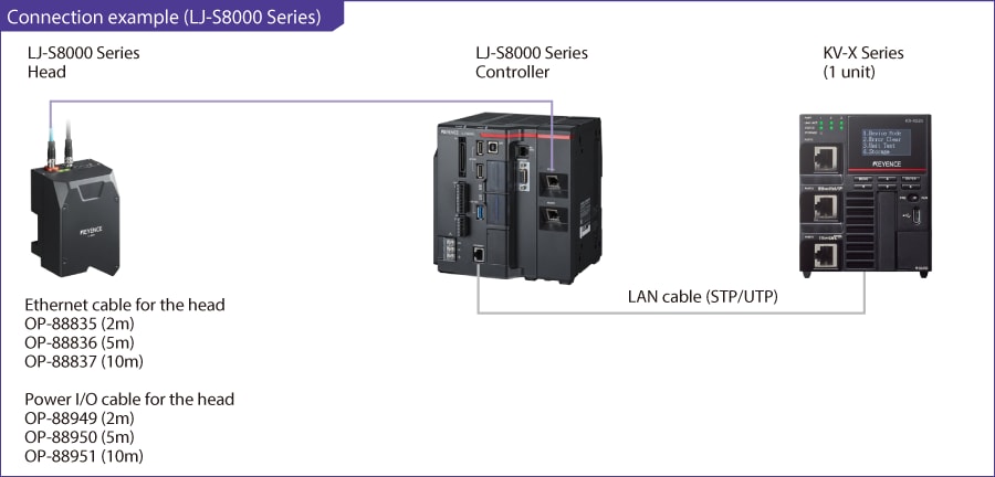
- *Instead of the CPU unit, connection to communication units such as KV-XLE02 is also possible.
- *Prepare a 24 VDC power supply and a monitor as well.
Trademark
Proper nouns such as product names described in this guide are registered trademarks or trademarks of their respective companies.
Step 2 : LJ-S8000 Series Connection Settings
Configure the LJ-S8000 Series network settings by connecting a USB mouse to the controller. This guide uses the example of a case in which the following IP addresses are assigned to KV-X Series and the LJ-S8000 Series.
[Reference]
Operate the LJ-S Series controller while confirming it on the analog RGB monitor or PC software (Terminal Software).
- IP address assigned to KV-X Series ……(Example: 192.168.0.10 [initial value])
- IP address assigned to the LJ-S8000 Series ……(Example: 192.168.0.1)
1. ON the setup screen of the LJ-S8000 Series, select[Global Settings] > [Communications &I/O] > [Network]. Configure the network settings as shown below and select [OK].
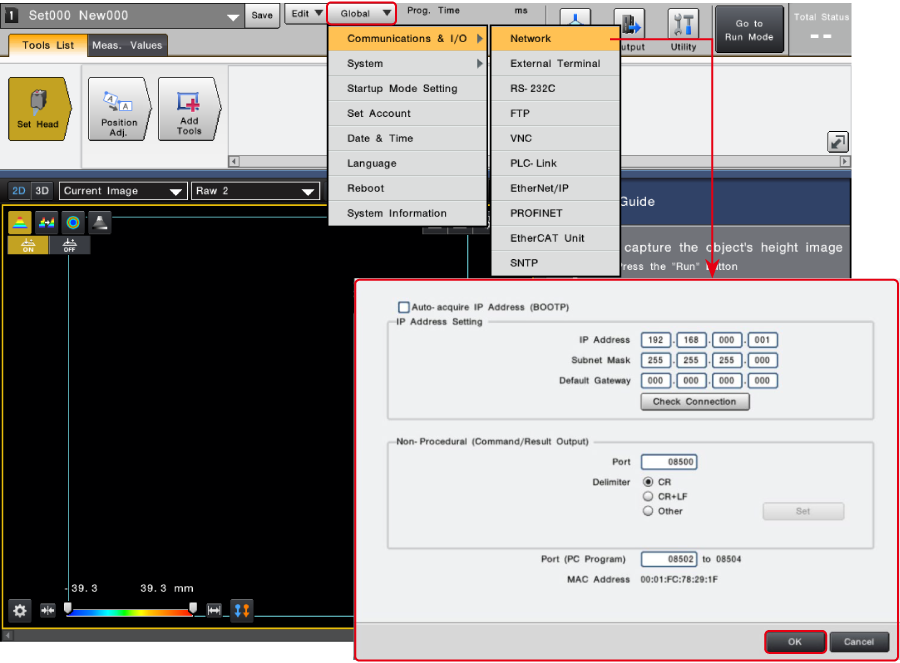
<Network settings>
| Auto-acquire IP address (BOOTP) | No check mark | |
|---|---|---|
| IP address setting | IP address | 192.168.000.001 |
| Subnet mask | 255.255.255.000 | |
| Default gateway | 000.000.000.000 | |
| Non-procedural communication (Command/Result Output) | Port | 08500 |
| Delimiter | CR | |
| PC Application Connection Port | 08502 to 08504 | |
If a confirmation dialog box is displayed after selecting [OK], select [Reboot Later].
2. Select [Global Settings] > [Communications & I/O] > [EtherNet/IP]. Configure the settings as shown below and select [OK].
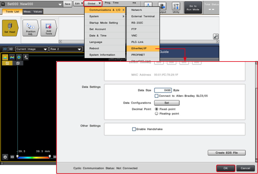
<EtherNet/IP settings>
| Enable EtherNet/IP communication | EtherNet/IP enabled | |
|---|---|---|
| Data Settings | Data Size | 496 bytes |
| Connect to Allen-Bradley SLC5/05 | No check mark | |
| Decimal Point | Fixed-point | |
| Other Settings | Enable Handshake | No check mark |
When the configuration is completed, a confirmation dialog box to restart the LJ-S8000 Series appears. Select [Save and Reboot Now].

The LJ-S8000 Series automatically restarts and the network settings are applied to the main body.
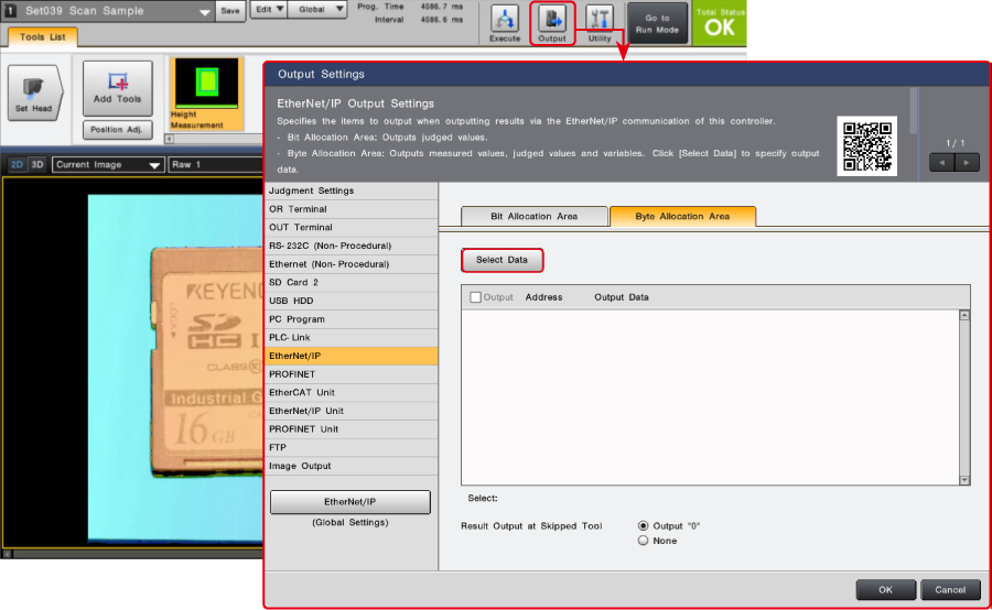
3. Click [Output Settings]. The [Output Settings] dialog box is displayed. Click [EtherNet/IP] > [Byte Allocation Area] and then [Select Targets].
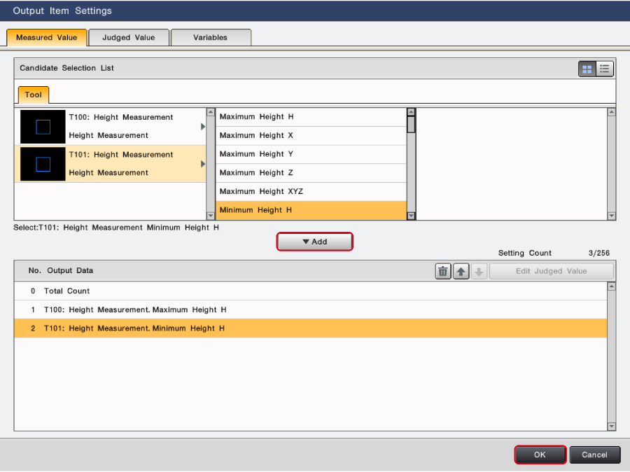
4. On the “Tool” tab, select the tool configured in advance. Parameters that can be measured with the selected tool are displayed. Select the parameters that you want to acquire through EtherNet/IP communication. Click [▼Add] and then [OK].
- *Configure the tool in advance. For details on how to configure the tool settings, see the LJ-S8000 Series User’s Manual.
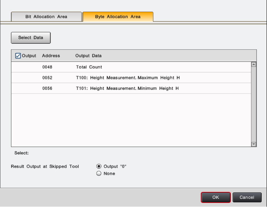
5. The assignment of the selected parameters is displayed. Configure the settings as shown below and select [OK].
- *To acquire information of bits such as Total status OK, select the [Bit Allocation Area] tab and paste the information of the bits in the output area of EtherNet/IP communication by following the same steps.
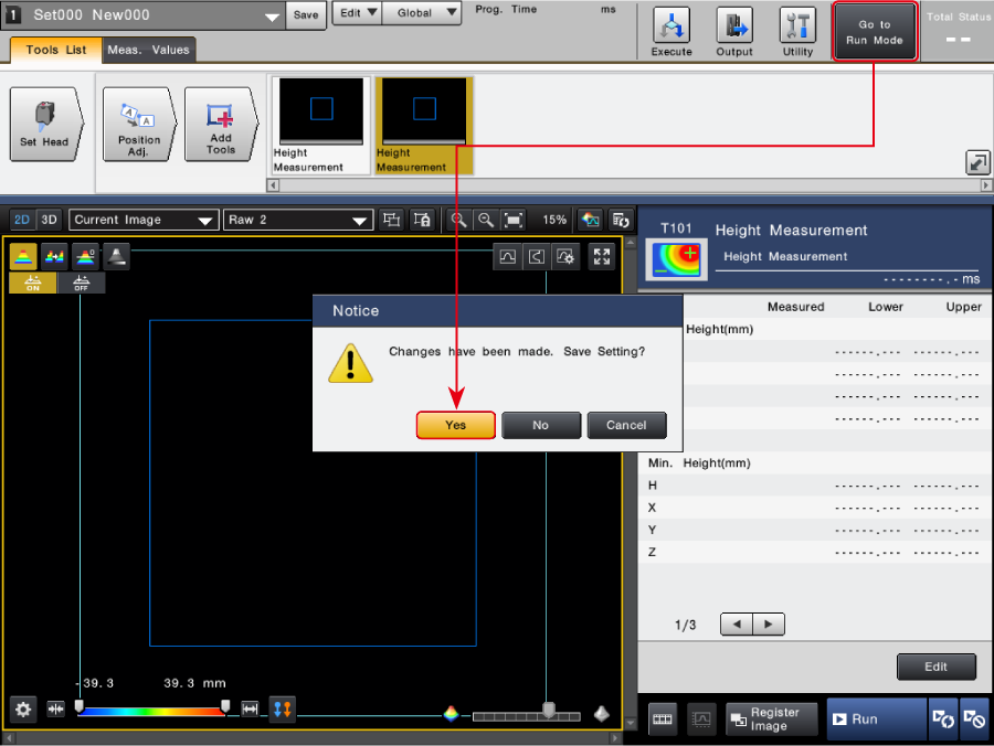
6. Click [Go to Run Mode]. The [Notice]/[Check] dialog box is displayed. Select [Yes] to save the settings and switch the controller to Run Mode.
Step 3 : KV-X Series Connection Settings
This section explains how to connect with a fictitious device called "Vendor Series". Replace the "Vender Series" with the device to be connected.
One point
For the KV Series with a CPU function version of 2.0 or later, variables can be assigned to the connection of EtherNet/IP.
When assigning variables to the connection of EtherNet/IP®, check the box of “Displays the variable setting dialog when updating the EtherNet/IP settings (E)” for “Other settings” of “System settings” on the “CPU system settings” dialog.
The “CPU system settings” dialog is displayed by selecting [Display (V)] ⇒ [CPU system settings (P)] from the ”KV STUDIO” menu.
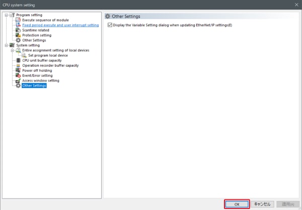
When the box of "Displays the variable setting dialog when updating the EtherNet/IP settings (E)" is checked, at the timing when the EtherNet/IP setting is updated and the changed content of the unit editor is confirmed, a dialog to assign variables to the connection is displayed.
1. Start up the KV STUDIO and create a new project. Set the model option to “KV-X520” and click [OK].
A [Confirm unit configuration setting] dialog box is displayed. Click [Yes (Y)].

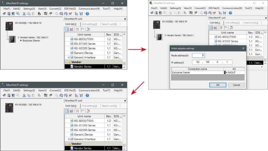
2. The unit editor is displayed. On the “Setup unit(2)” tab, click the icon of EtherNet/IP setting. A configuration type selection dialog box is displayed. Click [Manual (M)].

3. On the “Unit setting (2)” tab, set the IP address for KV-X Series. In this example, configure the setting as shown below.
* Step 4 needs to be performed to import a sensor setting file. When the sensor setting file has already been imported, proceed to Step 5.

4. Select [EDS file (D)] → [Reg (I)] to import the KEYENCE sensor setting file(ez1 file) or EDS file.
* Download the sensor setting file from the KEYENCE website.

5. With the KV-X Series and the EtherNet/IP devices connected using the Ethernet cable, select [File (F)] → [Auto configuration (S)] on the [EtherNet/IP settings] window.
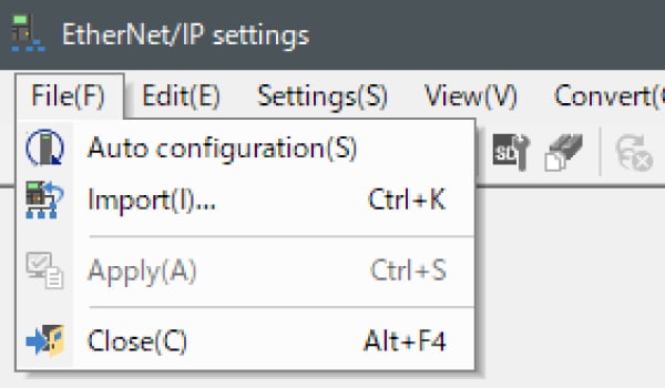
6. When the configuration on the unit editor differs from that of the actual device, a dialog for confirming transfer of the project is displayed. With the PC and KV-X Series connected using the USB cable, click [Yes (Y)].
7. When transfer of the project is completed, the [Search unit settings] dialog is displayed. Then click [Search (F)]. After the auto configuration is completed, "Vendor Series" is automatically registered. Then click [OK] to close the [EtherNet/IP settings] window.
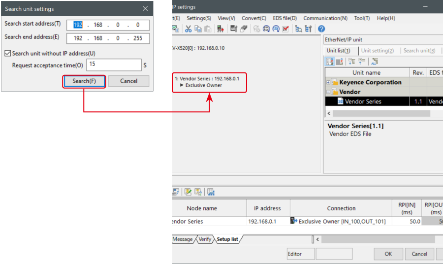
8. Click [OK] on the unit editor to exit.
One point
When the box of "Displays the variable setting dialog when updating the EtherNet/IP settings (E)" is checked, the [EtherNet/IP equipment Variable settings] dialog is displayed.
Enter the name of variable assigned to the connection, and click [OK].
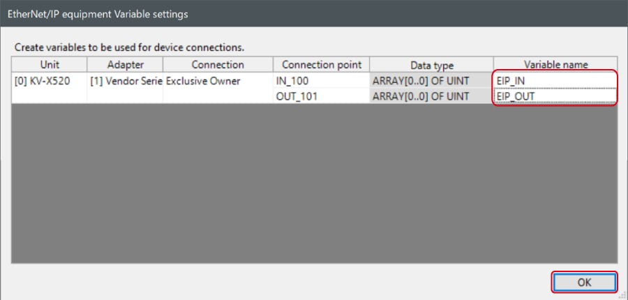
- The way of Device Configuration Settings manually
In the [Unit list (1)] tab of “EtherNet/IP Settings”, drag and drop "Vendor Series" and create a device configuration.
Transferring and Monitoring Setting Data
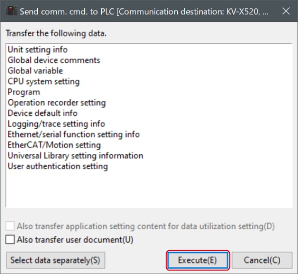
1. From the menu, select [Monitor/Simulator (N)] > [Transfer to PLC (W) → Monitor mode (C)].
In the [Send comm. cmd. to PLC] dialog box, click [Execute(E)].
2. If the following dialog box is displayed before and after transferring the data, click [Yes] both times.

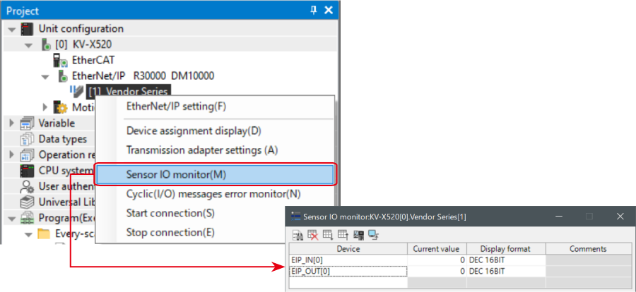
3. Right-click on “Vender Series” in the workspace, and select [Sensor IO monitor (M)].
Scores and other information can be easily monitored.
One point
The information can also be checked on a graph by starting up the real time chart monitor.
Right-click on “Sensor I/O monitor” and select [Real time chart monitor (H)].
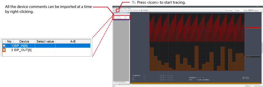
Range adjustment is not required since the real time chart monitor performs scaling automatically.
When Manipulating Parameters with a Program
Changing the Setting Values
The setting values of the sensors can be changed by the following two methods:
A : Change from a PC
B : Change from a ladder program
A : Change from a PC
To change the settings from a PC, use the transmission adapter function in KV STUDIO.
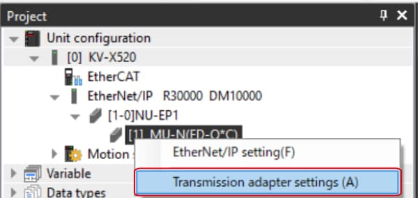
1. Expand the unit configuration in the workspace. Right-click on "Vender Series" and select [Transmission adapter settings (A)].
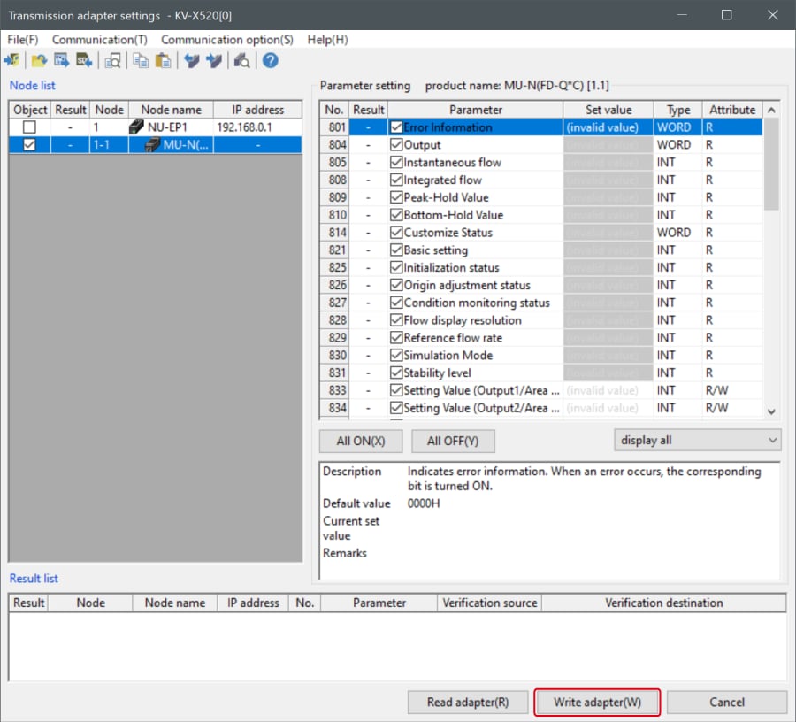
2. Place a check mark in Setting Value for "Vender Series" and enter the setting value.
Click [Write adapter (W)] to write the setting value to the sensor.
*To read the setting value of a sensor, select [Read adapter (R)].
B : Changed from a ladder program
Use message communication to change the setting values from a ladder program.
To perform message communication with KV STUDIO, use the sensor setting commands (SPWR [sensor parameter write] and SPRD [sensor parameter read]).

1. In Editor mode, create a ladder program as shown below.
* For the parameter numbers, refer to Parameter list.

2. Transfer the ladder program.
3. When MR100 is turned on, the setting value is changed.
* Store the setting value in DM4 ([Leading device to store results] + 4).
One point
RT (Real-Time) Edit function
When you use a ladder program, you can input device comments or parameter names directly to have input candidates be searched for and displayed automatically.

Step 4 : Confirmation of Communication Status
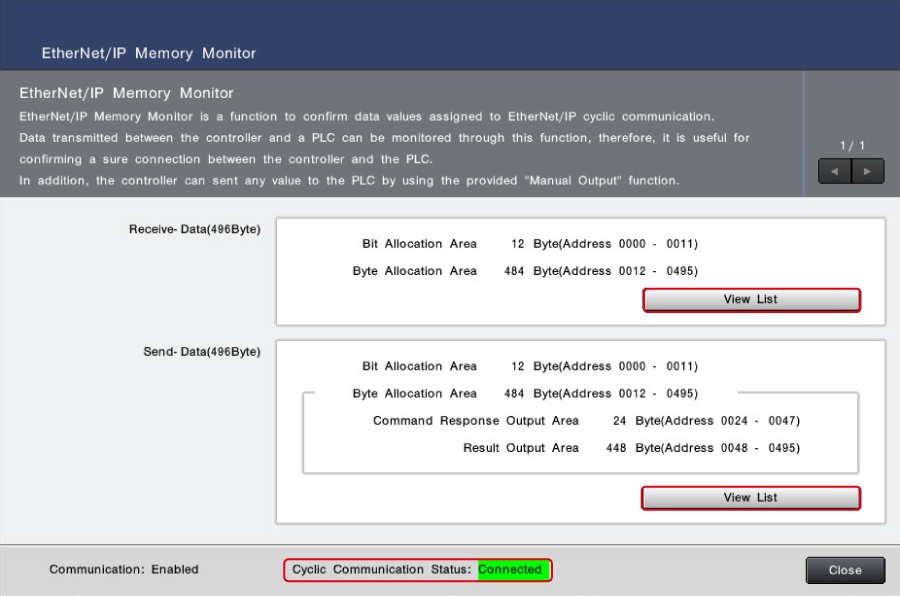
Click Utility > EtherNet/IP Memory Monitor.

Confirmation of Connection Status
When the cyclic communication status is “Connected,” cyclic communication is being established between the LJ-S Series and KV-X Series.
Reference
If the connection is unstable in an equipment configuration where multiple devices are connected via a HUB, in order to give priority to the establishment of EtherNet/IP communication connection, it is recommended to directly connect the LJ-S8000 Series and KV-X Series on a one-to-one basis and configure the settings according to this guide.
Confirmation of communication contents
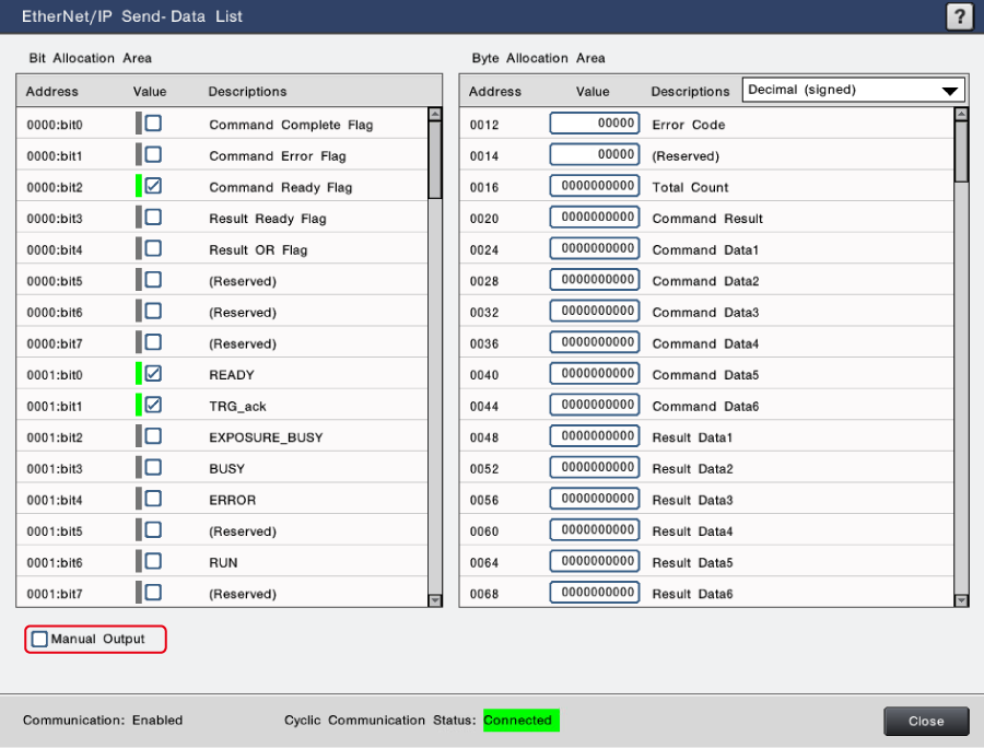
Click “View List” to confirm the sent/received data values of this system (LJ-S8000 Series).
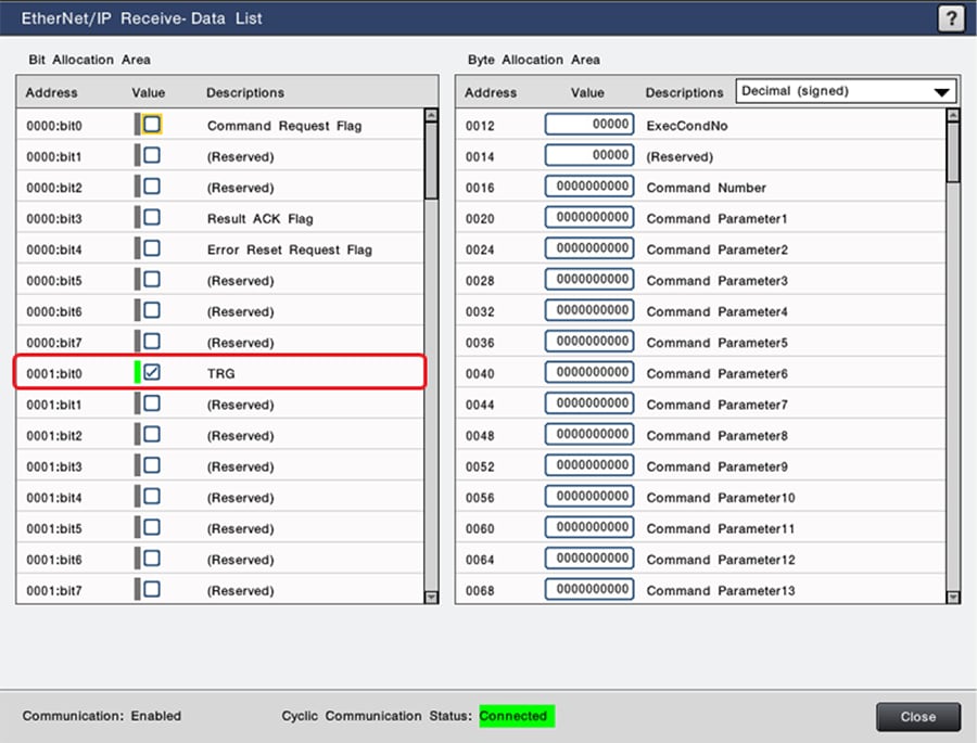
Click “View List” of the sent data of this system (LJ-S8000 Series).
The current output status of the LJ-S8000 Series can be checked. Putting a check mark next to “Manual Output” rewrites values optionally. You can confirm the communication status by checking if the rewritten values are correctly recognized on the sensor I/O monitor on the PLC side.
- *“Manual Output” is available in Setup Mode.
Step 5 : LJ-S8000 Series Control Procedure
What you can do with EtherNet/IP communication
The LJ-S8000 Series can output result data (measurement results, judgment results, etc.) with EtherNet/IP. In addition, it is also possible to input a trigger from PLC or switch between program settings using a command.
Assignment status of cyclic communication data
The following is the assignment status of cyclic communication data, which is the same as the contents that can be confirmed in “View List” of the received/sent data of this system (LJ-S8000 Series).
Output from LJ-S8000 Series to KV-X Series
[Note]
W**** shown in the table are examples of link relay and link register assignment to addresses when only one LJ-S8000 Series is connected to the KV-X Series CPU unit as EtherNet/IP equipment. If the initial value is set, LJ-S8000 is assigned in ascending order starting from W0.
|
Allocated device |
Member name | Data type |
|---|---|---|
| W00.0 | CmdComplete | BOOL |
| W00.1 | CmdError | BOOL |
| W00.2 | CmdReady | BOOL |
| W00.3 | ResultReady | BOOL |
| W00.4 | ResultOR | BOOL |
| W00.8 | READY | BOOL |
| W00.9 | TRG_ack | BOOL |
| W00.10 | ExposureBusy | BOOL |
| W00.11 | BUSY | BOOL |
| W00.12 | ERROR | BOOL |
| W00.14 | RUN | BOOL |
| W01.14 | OUTPUT_IMG_BUSY | BOOL |
| W01.15 | OUTPUT_IMG_STAUTS | BOOL |
| W02.0 to W05.15 | ToolJudgeVal | ARRAY[0..63] OF BOOL |
| W06 | ErrorCode | UINT |
| W08 to W09 | TotalCount | UDINT |
| W0A to W0B | CmdResult | UDINT |
| W0C to W0F7 | InputData | ARRAY[0..117] OF DINT |
Input from KV-X Series to LJ-S8000 Series
[Note]
W**** shown in the table are examples of link register assignment to addresses when only one LJ-S8000 Series is connected to the KV-X Series CPU unit as EtherNet/IP equipment.
|
Allocated device |
Member name | Data type |
|---|---|---|
| W0F8.0 | CmdRequest | BOOL |
| W0F8.3 | ResultAck | BOOL |
| W0F8.4 | ErrResetRequest | BOOL |
| W0F8.8 | TRG | BOOL |
| W0F9.0 | RESET | BOOL |
| W0F9.1 | EXT | BOOL |
| W0F9.2 | TEST | BOOL |
| W0FE | ExecCondNo | UINT |
| W0100 to W0101 | CmdNumber | UDINT |
| W0102 to W01EF | CmdParameter | ARRAY[0..118] OF UDINT |
Trigger input method
Turn ON TRG.

|
Allocated device |
Member name | Data type |
|---|---|---|
| W0F8.0 | CmdRequest | BOOL |
| W0F8.3 | ResultAck | BOOL |
| W0F8.4 | ErrResetRequest | BOOL |
| W0F8.8 | TRG | BOOL |
| W0F9.0 | RESET | BOOL |
| W0F9.1 | EXT | BOOL |
| W0F9.2 | TEST | BOOL |
How to confirm result update
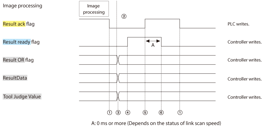
Turning ON trigger input starts capture and measurement. After the measurement results are determined, all data is updated.
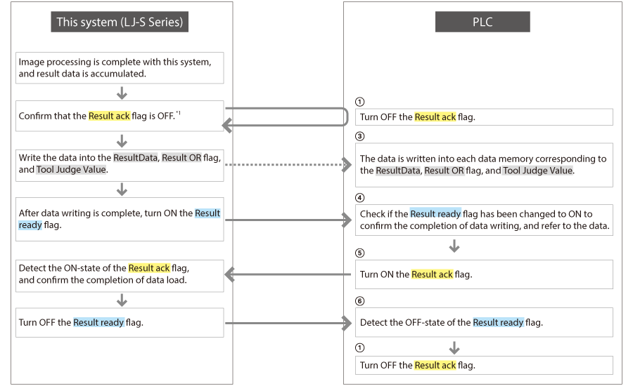
If a check mark is put next to “Enable Handshake,” refer to the measurement result data after the Result ready flag is turned ON. After that, turn OFF the Result ack flag. The controller updates the next data after confirming that the Result ack flag is OFF. In “Output Settings,” specify what items of the measured values should be output.
- *Data is output only during Run Mode. (Data is not output in Setup Mode.)
For a detailed flow, refer to the following.
Reference
- If output is executed with the Result ack flag ON, data is stored in the output buffer but not written into ResultData. The data stored in the buffer is written into it when the Result ack flag is turned OFF. Please note that if the inspection flow is continued to be executed with the Result ack flag ON, the output buffer overflows and output is skipped.
- If the handshake is OFF, output data is overwritten and updated without confirming that the Result ack flag is OFF. If you want to use turning on of the Result ready flag as the synchronizing signal of data reference, turn ON the Result ack flag at each output to turn OFF the Result ready flag.
Timing chart
Reference
Result OR is updated depending on the result output that uses EtherNet/IP as the output destination. If Result OR is used,it is necessary to configure output settings so that at least a piece of data is output to EtherNet/ IP.
<Settings of [Enable Handshake]>
Select Global Settings > Communications & I/O > EtherNet/IP to configure the settings. (No check mark by default)

<Decimal Point>
Select the data expression method used in result data output or commands handling decimals.
-
Fixed-point (Default value)
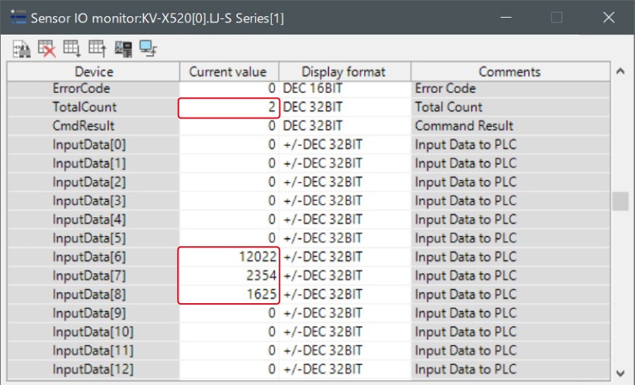
Data 1000 times as large as the original data is handled as 32-bit signed integer data. Example: 1.234 mm is output as 1234. - Floating-point: Handled as 32-bit single-precision floating point data.
Select Global Settings > Communications & I/O > EtherNet/IP to configure the settings.

Example: 1.234 mm is output as 1234.
When measurement count: 2, 1st measured value: 12.022, 2nd measured value :2.354, 3rd measured value:1.625
Command control
Store the command value (command No. and command parameter) that you want to use for the command input region. After the completion of command value storing, turn ON Command request. After the completion of command execution, Command complete is turned ON.
For a detailed flow, refer to the following.
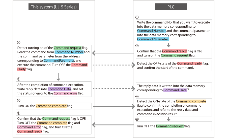
Timing chart
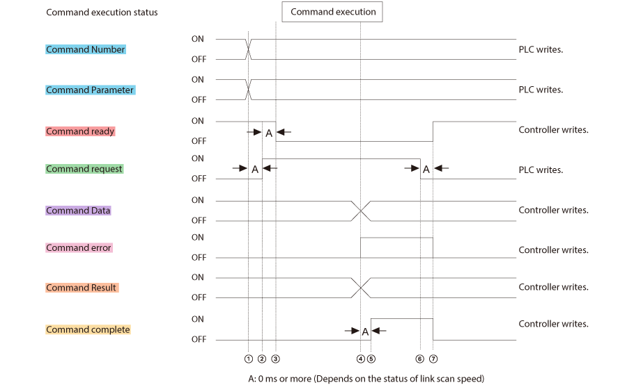
<Available commands>
Representative commands are shown blow. For details, see Chapter 9 “List of Commands” in the User’s Manual. Commands that are the same in “number specification command” can be used.
- Issue trigger
- Switch to Run Mode,switch to Setup Mode
- Reset
- Save settings (See page 21)
- Clear error
- Switch run screen
- Load Run/Setup Mode
- Load program setting (See page 23)
- Switch program setting (See page 24)
- Write execution condition, load execution condition
- Permit/prohibit trigger input
- Clear statistical data, export statistical data
- Screen capture
- Rewrite judgment condition (See page 26) , etc.
Command execution example (12: Save settings)
Saves the current program setting and Global Settings.
Number specification command format
Number specification command No. is “12”
- Sending
Word device * 12 - *Word device at the beginning (command address)
- Receiving
Word device * Return value Execution result - *Word device at the beginning (command result address)
Execution result
- 0: Successful
- 22: When there is an extra parameter
- 03: When there is no SD card or it is inaccessible
<Example of sensor IO monitor>
Enter a value as shown below.
Command Number = 12 (Number specification command No.12)

Turn ON Command request.
The settings are saved.

Confirm a change in the variables to which the values of Command complete, Command error, and Command result are assigned.

The ON-state of Cmd complete means that the command to save settings has been executed.

Cmd result
→ Execution result 0: Successful
(If it fails, an error code is displayed.)
-
After the completion of the command
After the completion of the command, turn OFF Command Request. This makes Command ready turn ON to allow the next command to be executed.
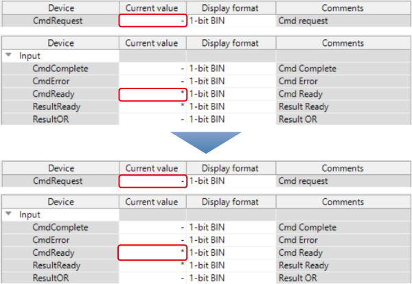
Command execution example (25: Load program setting)
Returns the currently set SD card No. and program setting No.
Number specification command format
Number specification command No. is “25”
- Sending
Word device * 25 - *Word device at the beginning (command address)
- Receiving
Word device * +1 +2 +3 +4 +5 Return value Execution result d nnn - *Word device at the beginning (command result address)
<Example of sensor IO monitor>
Enter a value as shown below. (Example of current program setting No.12)
Parameters
-
d: SD card No. (1to 2)
1: SD1
2: SD2 - nnn: Program setting (0 to 999)
Execution result
- 0: Successful
- 22: When there is an extra parameter
Command Number = 25 (Number specification command No.25)

Turn ON Command request.
The command (Load program setting) is executed.

Confirm a change in the values of Command complete, Command error, Command result, and Command Data.
The SD card No.(1 or2) is stored in Command Data1, and the program setting No. (0 to 999)is stored in Command Data2.


Cmd result
→ Execution result 0: Successful
Cmd Data1
1 → SD1
Cmd Data2
12 → Program setting No.12
The steps after the completion of the command are the same as those of the command execution example (12: Save settings).
Command execution example (24: Switch program setting)
Switches the program setting to the specified No.
The parameter to specify varies depending on whether the program setting of the switching destination is located in SD1 or SD2.
Number specification command format
Number specification command No. is “24”
- Sending
Word device * +1 +2 +3 +4 +5 24 d nnn - *Word device at the beginning (command address)
- Receiving
Word device * Return value Execution result - *Word device at the beginning (command result address)
Parameters
- d: SD card No. (1 to 2), 1: SD1, 2: SD2
- nnn: Program setting (0 to 999)
<Example of sensor IO monitor>
- Switch the 30 program setting to SD1 No.12.
Execution result
- 0: Successful
- 22: When the number of parameters and the parameter range are different
-
03:
- When there is no program setting
- When there is no SD card or it is inaccessible
- When the program setting of the switching destination is locked by a controller ID
Enter each value as shown below.
Command number = 24 (Number specification command No.24)
Command Parameter1 = 1 (d: SD card No.SD1: 1, SD2: 2)
Command Parameter2 = 12 (nnn: Program setting (0 to 999))

Turn ON Command request.
The command(Switch SD1 program setting No.) is executed.

Confirm a change in the values of Command complete, Command error, and Command result.
- When the command is successful: Command complete turns “1,” and Command error turns “0.”

The ON-state of Cmd complete means that the command execution is complete.

Cmd result
→ Execution result 0: Successful
- When the command fails: Command complete turns“1,” and Command error also turns “1.” In addition,an error code is written into Command result.

Command result turns 3 in the following cases. (According to the details of commands described in the User’s Manual)
- When there is no program setting/when there is no SD card or it is inaccessible/when the program setting of the switching destination is locked by a controller ID

The steps after the completion of the command are the same as those of the command execution example (12: Save settings).
Command execution example (45: Rewrite judgment condition)
Rewrites the upper limit value and the lower limit value of the judgment condition of the specified tool.
Number specification command format
Number specification command No. is “45”
- Sending
Word device * +1 +2 +3 +4 +5 +6 +7 +8 +9 45 nnn aaa b mmm - *Word device at the beginning (command address)
- Receiving
Word device * Return value Execution result - *Word device at the beginning (command result address)
Execution result
- 0: Successful
- 22: When the number of parameters, the number of digits, and the parameter range are different
-
03:
- When the specified tool does not have the specified type
- When a screen (custom menu, statistical analysis, etc.)on which judgment conditions are rewritable is open
- When the value to rewrite is incorrect
<Example of sensor IO monitor>
Enter a value as shown below. (For the tool No. 100, set the upper limit value of the maximum height H in the height measurement to 1.234 mm.)
Parameters
- nnn: Tool No. (100 to 199)
Reference
When Multiple Area Mode is ON, the area No. can be specified by specifying the following values.
100 * Tool No. (100 to 199) + Area No. (0 to 31)
If the area No. is not specified (specified with a value between 100 and 199), the area with the lowest No. becomes the target.
- aaa: Item ID of judgment condition type (PageA-56)
- b: Upper limit (0)/lower limit (1) specification
-
mmm: Value of judgment condition (In the case of a number specification command, it varies depending on the settings of PLC link or EtherNet/IP, PROFINET, and EtherCAT “Decimal Point.”)
- When “Fixed-point” is selected: 32-bit signed integer data 1000 times as large as the set value
- When “Floating-point” is selected: Single-precision floating point data
Command Number = 45 (Number specification command No.45)
Command Parameter1 = 100 (nnn: Tool No. 100 to 199)
Command Parameter2 = 8019 (aaa:Item ID of judgment condition type *See the output item correspondence table.)
Command Parameter3 = 0(b: Upper limit: 0, lower limit: 1)
Command Parameter4 = 1234 (mmm: Value of judgment condition)

Turn ON Command request.
The command (Load program setting) is executed.

Confirm a change in the values of Command complete, Command error, and Command result.

The ON-state of Cmd complete means that the command execution is complete.

Cmd result
→ Execution result 0: Successful
The steps after the completion of the command are the same as those of the command execution example (12: Save settings).
<Output item correspondence table>
The output item correspondence table is shown in the appendix of the User’s Manual. Use these item ID numbers to send commands.
| Tool | Symbol |
Indication of measure- ment item selection |
Indication of sorting selection |
Measurement data format |
Scaling target |
Label speci- fication |
Item ID |
|---|---|---|---|---|---|---|---|
| Common | EXAC | Execution count | Integer 10 digits | - | × | - | |
| OKAC | OK count | Integer 10 digits | - | × | - | ||
| NGAC | NG count | Integer 10 digits | - | × | - | ||
| TERR | Execution error | Integer 1 digits | - | × | - | ||
| TEID | Execution error ID | Integer 7 digits | - | × | - | ||
| EXTM | Execution time | Integer 7 digits, decimal 3 digits | - | × | - | ||
| Height measurement | MXX* | Maximum height X | MS,AB,EC,JG,HL,LL | Signed, integer 5 digits, decimal 3 digits | X | × | 8051 |
| MXY* | Maximum height Y | MS,AB,EC,JG,HL,LL | Signed, integer 5 digits, decimal 3 digits | Y | × | 8053 | |
| MXZ* | Maximum height Z | MS,AB,EC,JG,HL,LL | Signed, integer 5 digits, decimal 3 digits | - | × | 8055 | |
| MXH* | Maximum height H | MS,JG,HL,LL | Signed, integer 5 digits, decimal 3 digits | - | × | 8019 | |
| MXXYZ* | Maximum height XYZ | MS,AB,EC | Signed, integer 5 digits, decimal 3 digits | - | × | - | |
| MNX* | Minimum height X | MS,AB,EC,JG,HL,LL | Signed, integer 5 digits, decimal 3 digits | X | × | 8058 | |
| MNY* | Minimum height Y | MS,AB,EC,JG,HL,LL | Signed, integer 5 digits, decimal 3 digits | Y | × | 8060 | |
| MNZ* | Minimum height Z | MS,AB,EC,JG,HL,LL | Signed, integer 5 digits, decimal 3 digits | - | × | 8062 | |
| MNH* | Minimum height H | MS,JG,HL,LL | Signed, integer 5 digits, decimal 3 digits | - | × | 8020 | |
Troubleshooting
If it does not work properly
Want to check if EtherNet/IP connection is normal.
From the controller, select “Global Settings”> “Communications & I/O” > “EtherNet/IP” and confirm “Cyclic Communication Status” shown in the bottom part of the “EtherNet/IP” screen. If “Not Connected” is displayed here, it means that the establishment of communication failed. Please reconfirm the cable connection status, IP address, communication settings on the PLC side, etc.
Reference
If the system is connected to Allen-Bradley SLC5/05, “Not Connected” is displayed even if the connection is normal because cyclic communication is not performed.
The Result OR flag is not output.
The Result OR flag is updated depending on the result output that uses EtherNet/IP as the output destination. If the Result OR flag is used, at least a piece of data needs to be output from EtherNet/IP.
The Result ready flag remains ON and unchanged.
There is a possibility that the Result ack flag is being controlled improperly. The Result ready flag turns OFF after recognizing turning on of the Result ack flag in sending (receiving on this system).
This applies to both handshake ON and OFF.
When data is loaded based on a rising change of STO output from an external terminal, correct data cannot be acquired.
Because STO is a strobe signal for terminal output data, it cannot be used as a strobe signal for data output from others.
For the timing of data load in EtherNet/IP, refer to the Result ready flag.
The updating cycle is long. The output result seems to be the previous result.
Please confirm the cyclic communication cycle on the PLC side.
Error message
| Message | Cause | Measures |
Error factor No. |
|---|---|---|---|
| Communication with EtherNet/IP failed. | Cyclic communication was disconnected. (It is automatically restored if possible.) |
|
13601 |
| Output to EtherNet/IP failed because the output buffer reached its capacity. | The output buffer to EtherNet/IP has reached its capacity. | Please reconfigure the RPI settings so that the pace of data output to EtherNet/IP exceeds the pace of data output from the flow, or lengthen the interval between triggers. (Results are not output when the output buffer has reached its capacity.) | 13602 |
| The result output of EtherNet/IP communication was skipped because of a delay in handshake. | With the handshake of EtherNet/IP ON, result output to EtherNet/IP was skipped because of a delay in handshake. | Please reconfigure the RPI settings so that the pace of data output to EtherNet/IP exceeds the pace of data output from the tool, or lengthen the interval between triggers. (Results are not output when the output buffer has reached its capacity.) | 13603 |

