KV-X Series × IV4 Series
EtherNet/IP™ Connection Guide
Return to KV Series Connection Guide
KV-X Series × IV4 Series EtherNet/IP™ Connection Guide
IV4 Series

Contents
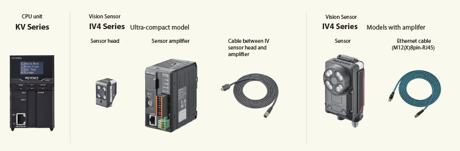
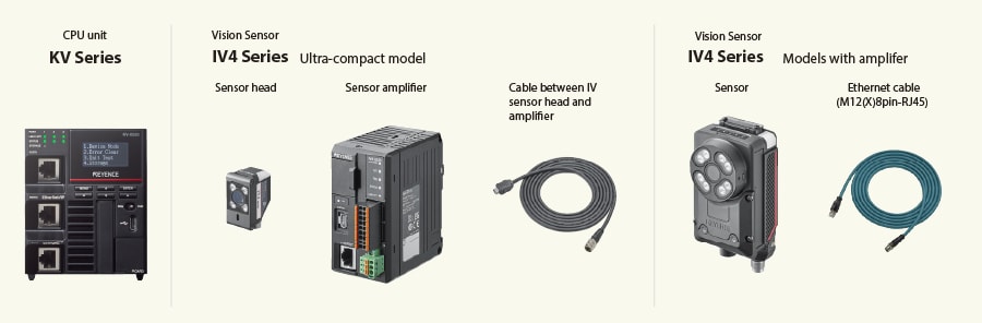
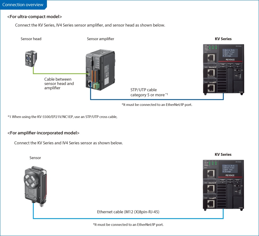
Step 1 : Devices Required for Connection
Step 2 : IV4 Series [EtherNet/IP] Settings
Configure the IV4 Series network settings using the IV Smart Navigator. As an example, this guide describes the procedure to assign the following IP addresses to the PC, KV Series, and IV4 Series. Set an IP address for PC beforehand.
- IP address to be assigned to the PC: (example) 192.168.0.200
- IP address to be assigned to the KV Series: (example) 192.168.0.10 (initial value)
- IP address to be assigned to the IV4 Series: (example) 192.168.0.1
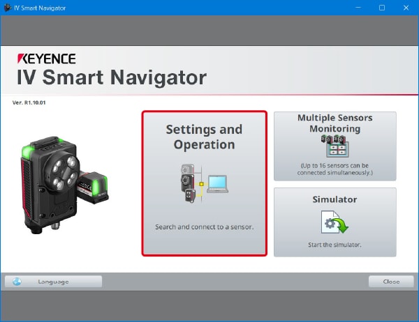
1. Using a LAN cable, connect the PC and the amplifier of the IV4 Series. Start up the IV Smart Navigator, and click [Settings and Operation].
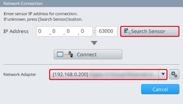
2. Select the IP address of the PC set beforehand for "Network adapter", and click [Search Sensor].
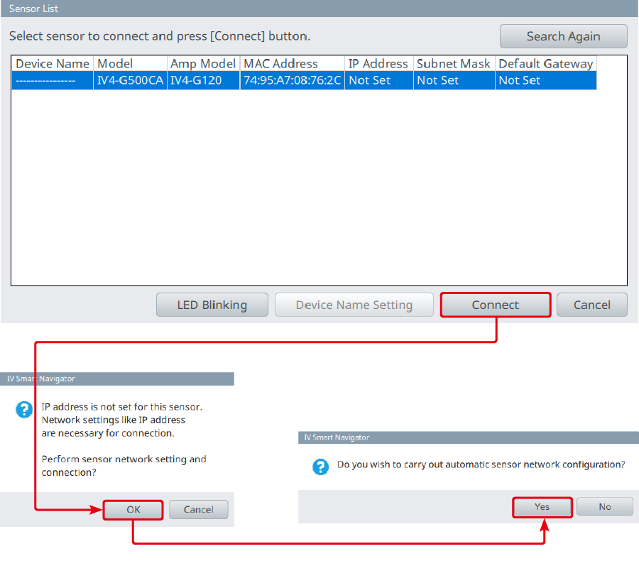
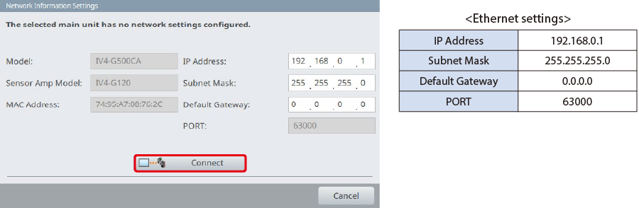
3. The IV4 Series connected with the LAN cable is displayed. Click [Connect], and then click [OK].
4. Set the IP address to be assigned to the IV4 Series. In this example, enter the following values, and click [Connect].
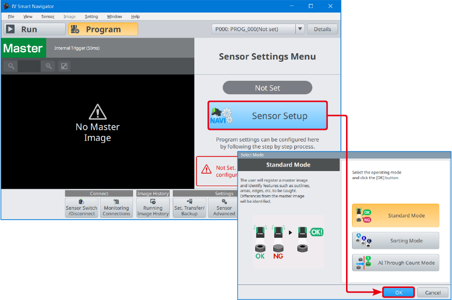
5. The main screen is displayed. Click [Sensor Setup], and adjust the brightness, register the master image, etc. This guide describes the procedure when "Standard Mode" is selected as a mode used for judgment. For details about the sensor settings, refer to the "IV4 Series User’s Manual".
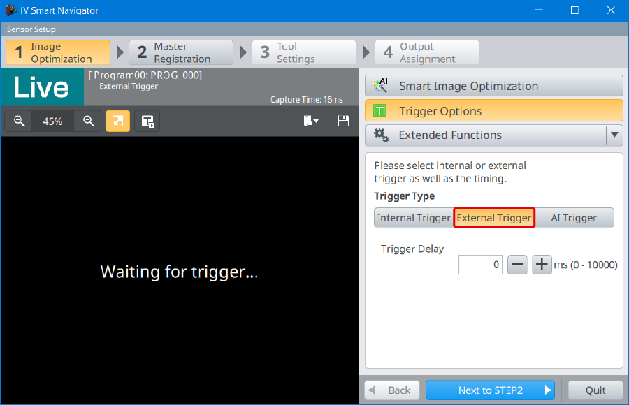
- *When controlling the imaging timing on the KV Series, set the trigger condition to "External Trigger".
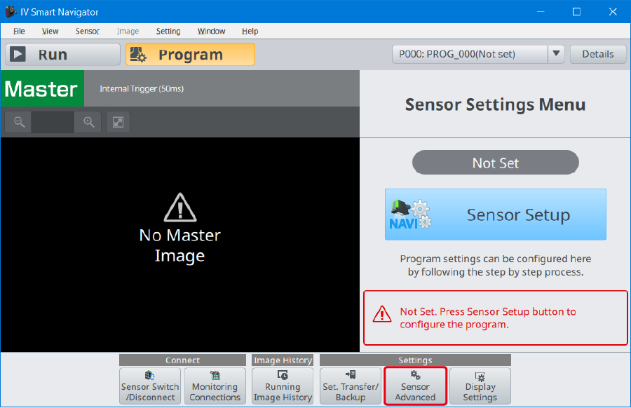
6. After the sensor settings are completed, the main screen is displayed again. Click [Sensor Advanced].
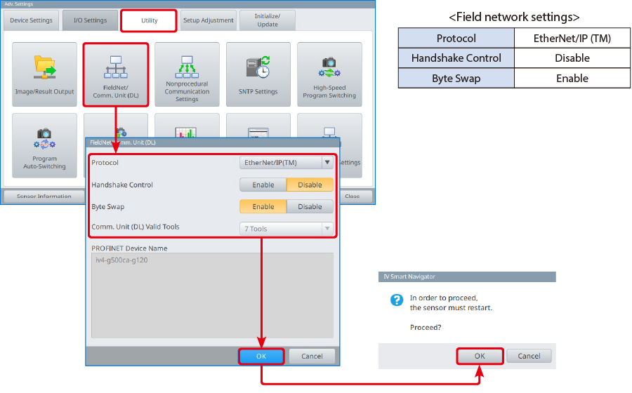
7. Open the "Utility" tab, and click [FieldNet/Comm. Unit (DL)]. The [FieldNet/Comm. Unit (DL)] dialog is displayed. Configure the settings as shown below. Click [OK], and then [OK]. The settings are transfered, and the IV4 Series automatically restarts to reflect the settings.
Step 3 : KV-X Series Connection Settings
This section explains how to connect with a fictitious device called "Vendor Series". Replace the "Vender Series" with the device to be connected.
One point
For the KV Series with a CPU function version of 2.0 or later, variables can be assigned to the connection of EtherNet/IP.
When assigning variables to the connection of EtherNet/IP®, check the box of “Displays the variable setting dialog when updating the EtherNet/IP settings (E)” for “Other settings” of “System settings” on the “CPU system settings” dialog.
The “CPU system settings” dialog is displayed by selecting [Display (V)] ⇒ [CPU system settings (P)] from the ”KV STUDIO” menu.
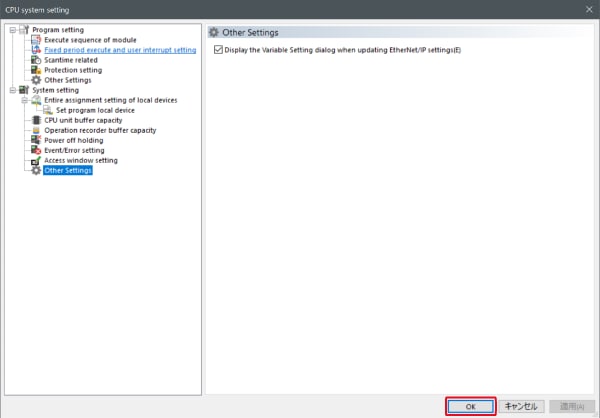
When the box of "Displays the variable setting dialog when updating the EtherNet/IP settings (E)" is checked, at the timing when the EtherNet/IP setting is updated and the changed content of the unit editor is confirmed, a dialog to assign variables to the connection is displayed.
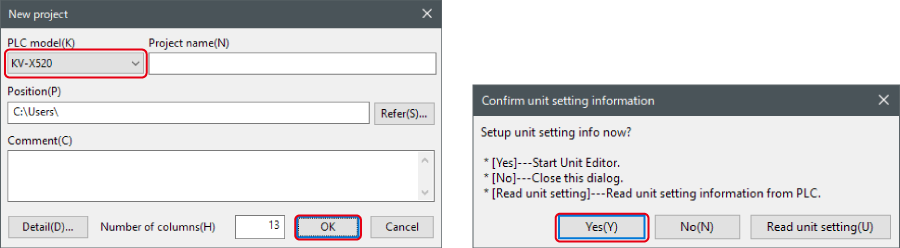
1. Start up the KV STUDIO and create a new project. Set the model option to “KV-X520” and click [OK].
A [Confirm unit configuration setting] dialog box is displayed. Click [Yes (Y)].
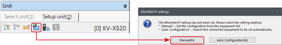
2. The unit editor is displayed. On the “Setup unit(2)” tab, click the icon of EtherNet/IP setting. A configuration type selection dialog box is displayed. Click [Manual (M)].
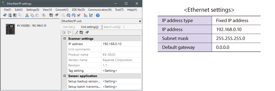
3. On the “Unit setting (2)” tab, set the IP address for KV-X Series. In this example, configure the setting as shown below.
* Step 4 needs to be performed to import a sensor setting file. When the sensor setting file has already been imported, proceed to Step 5.
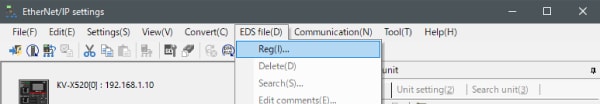
4. Select [EDS file (D)] → [Reg (I)] to import the KEYENCE sensor setting file(ez1 file) or EDS file.
* Download the sensor setting file from the KEYENCE website.
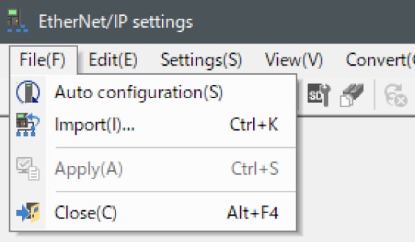
5. With the KV-X Series and the EtherNet/IP devices connected using the Ethernet cable, select [File (F)] → [Auto configuration (S)] on the [EtherNet/IP settings] window.
6. When the configuration on the unit editor differs from that of the actual device, a dialog for confirming transfer of the project is displayed. With the PC and KV-X Series connected using the USB cable, click [Yes (Y)].
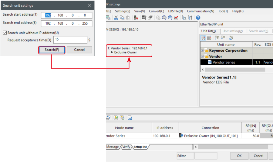
7. When transfer of the project is completed, the [Search unit settings] dialog is displayed. Then click [Search (F)]. After the auto configuration is completed, "Vendor Series" is automatically registered. Then click [OK] to close the [EtherNet/IP settings] window.
8. Click [OK] on the unit editor to exit.
One point
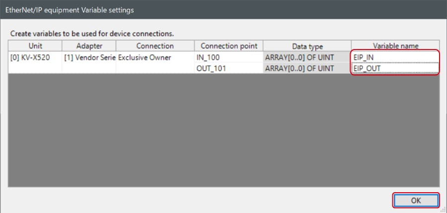
When the box of "Displays the variable setting dialog when updating the EtherNet/IP settings (E)" is checked, the [EtherNet/IP equipment Variable settings] dialog is displayed.
Enter the name of variable assigned to the connection, and click [OK].
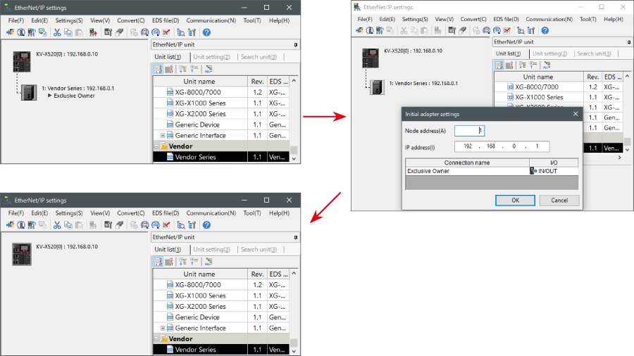
- The way of Device Configuration Settings manually
In the [Unit list (1)] tab of “EtherNet/IP Settings”, drag and drop "Vendor Series" and create a device configuration.
Transferring and Monitoring Setting Data
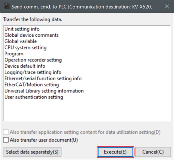
1. From the menu, select [Monitor/Simulator (N)] > [Transfer to PLC (W) → Monitor mode (C)].
In the [Send comm. cmd. to PLC] dialog box, click [Execute(E)].
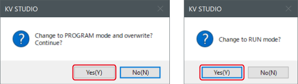
2. If the following dialog box is displayed before and after transferring the data, click [Yes] both times.
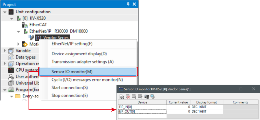
3. Right-click on “Vender Series” in the workspace, and select [Sensor IO monitor (M)].
Scores and other information can be easily monitored.
One point
The information can also be checked on a graph by starting up the real time chart monitor.
Right-click on “Sensor I/O monitor” and select [Real time chart monitor (H)].
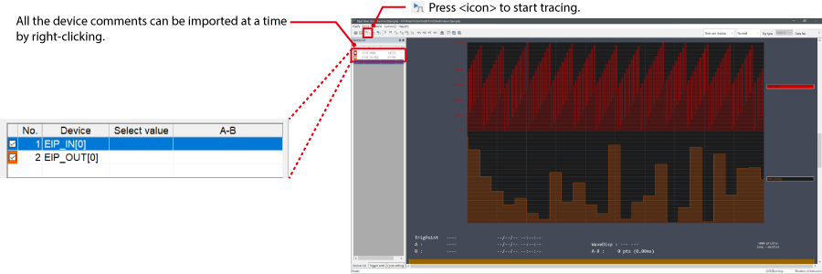
Range adjustment is not required since the real time chart monitor performs scaling automatically.
When Manipulating Parameters with a Program
Changing the Setting Values
The setting values of the sensors can be changed by the following two methods:
A : Change from a PC
B : Change from a ladder program
A : Change from a PC
To change the settings from a PC, use the transmission adapter function in KV STUDIO.
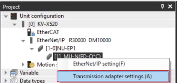
1. Expand the unit configuration in the workspace. Right-click on "Vender Series" and select [Transmission adapter settings (A)].
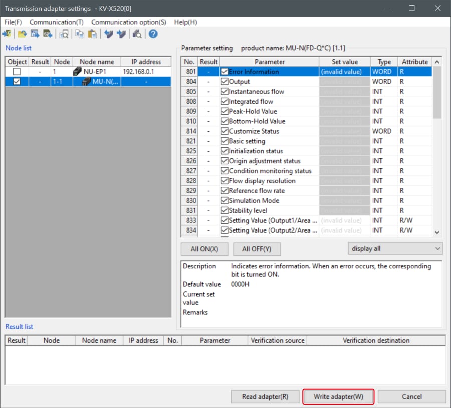
2. Place a check mark in Setting Value for "Vender Series" and enter the setting value.
Click [Write adapter (W)] to write the setting value to the sensor.
*To read the setting value of a sensor, select [Read adapter (R)].
B : Changed from a ladder program
Use message communication to change the setting values from a ladder program.
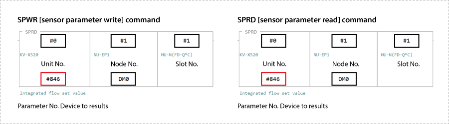
To perform message communication with KV STUDIO, use the sensor setting commands (SPWR [sensor parameter write] and SPRD [sensor parameter read]).
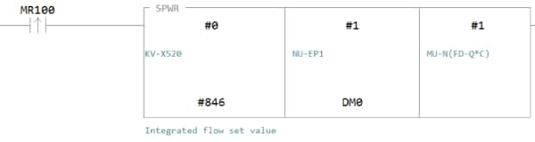
1. In Editor mode, create a ladder program as shown below.
* For the parameter numbers, refer to Parameter list.
2. Transfer the ladder program.
3. When MR100 is turned on, the setting value is changed.
* Store the setting value in DM4 ([Leading device to store results] + 4).
One point
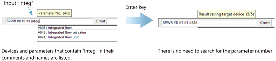
RT (Real-Time) Edit function
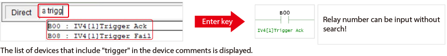
When you use a ladder program, you can input device comments or parameter names directly to have input candidates be searched for and displayed automatically.
Extra 1 : Memory Mapping
List of parameters that can be obtained in cyclic communication
Since the parameters that can be obtained during cyclic communication are automatically updated between the KV Series and IV4 Series at a constant period, a program for reading and writing data is not required. Each device map in the following cases is shown in the table below.
- - When B000 and W000 are allocated to the leading device of the link devices
- - When W000 (leading device of the link devices) is allocated to variable
IV4 Series → KV Series
| Address (byte) | Bit | When allocated to the devices | When allocated to the variables | |||
|---|---|---|---|---|---|---|
|
Allocated device |
Name |
Allocated device |
Member name | Data type | ||
| 0 | 0 | B00 | Trigger response | W00.0 | TriggerResp | BOOL |
| 1 | B01 | Master registration response | W00.1 | MasterRegResp | BOOL | |
| 2 | B02 | Program switching response | W00.2 | ProgramSwitchResp | BOOL | |
| 3 | B03 | Warning clear response | W00.3 | WarningClrResp | BOOL | |
| 4 | B04 | Statistics reset response | W00.4 | StatResetResp | BOOL | |
| 5 | B05 | Judgment/buffer clear response | W00.5 | Rslt_BufferClrResp | BOOL | |
| 6 | B06 | SD save stop response | W00.6 | SD_SavingStopResp | BOOL | |
| 7 | B07 | Setting value change response | W00.7 | SetValChgResp | BOOL | |
| 1 | 0 | B08 | Trigger failure | W00.8 | TriggerFail | BOOL |
| 1 | B09 | Master registration failure | W00.9 | MasterRegFail | BOOL | |
| 2 | B0A | Program switching failure | W00.10 | ProgramSwitchFail | BOOL | |
| 3 | B0B | Count-up input response | W00.11 | CountUpInputResp | BOOL | |
| 4 | B0C | Count reset response | W00.12 | CountResetResp | BOOL | |
| 5 | B0D | System reservation | W00.13 | - | ||
| 6 | B0E | SD save stop failure | W00.14 | SD_SavingStopFail | BOOL | |
| 7 | B0F | Setting value change failure | W00.15 | SetValChgFail | BOOL | |
| 2 | 0 | B010 | Result acquisition possible | W01.0 | ResultAvailable | BOOL |
| 1 | B011 | Result update completion | W01.1 | ResultUpdateComp | BOOL | |
| 2 | B012 | Busy | W01.2 | BUSY | BOOL | |
| 3 | B013 | Imaging state | W01.3 | ImagingStatus | BOOL | |
| 4 | B014 | Operation | W01.4 | RUN | BOOL | |
| 5 | B015 | Ready | W01.5 | Ready | BOOL | |
| 6 | B016 | Trigger ready | W01.6 | TriggerReady | BOOL | |
| 7 | B017 | SD card recognition state | W01.7 | SD_Status | BOOL | |
| 3 | 0 | B018 | Sorting mode information | W01.8 | ClassificationMode | BOOL |
| 1 | B019 | System reservation | W01.9 | - | ||
| 2 | B01A | Passing count mode operation state | W01.10 | AI_ThroughCountStatus | BOOL | |
| 3 | B01B | System reservation | W01.11 | - | ||
| 4 | B01C | SD card capacity shortage | W01.12 | SD_NoSpace | BOOL | |
| 5 | B01D | Buffer over run | W01.13 | BufferOverRun | BOOL | |
| 6 | B01E | Warning | W01.14 | Warning | BOOL | |
| 7 | B01F | Error | W01.15 | Error | BOOL | |
| 4 | 0 | B020 | Total judgment OK | W02.0 | OverallJudgeOK | BOOL |
| 1 | B021 | Position correction | W02.1 | PositionCorrection | BOOL | |
| 2 | B022 | LOGIC1 | W02.2 | LOGIC1 | BOOL | |
| 3 | B023 | LOGIC2 | W02.3 | LOGIC2 | BOOL | |
| 4 | B024 | LOGIC3 | W02.4 | LOGIC3 | BOOL | |
| 5 | B025 | LOGIC4 | W02.5 | LOGIC4 | BOOL | |
| 6 | B026 | Total judgment NG | W02.6 | OverallJudgeNG | BOOL | |
| 7 | B027 | System reservation | W02.7 | - | ||
| 5 | 0 | B028 | LOGIC5 | W02.8 | LOGIC5 | BOOL |
| 1 | B029 | LOGIC6 | W02.9 | LOGIC6 | BOOL | |
| 2 | B02A | LOGIC7 | W02.10 | LOGIC7 | BOOL | |
| 3 | B02B | LOGIC8 | W02.11 | LOGIC8 | BOOL | |
| 4 | B02C | System reservation | W02.12 | - | ||
| 5 | B02D | W02.13 | ||||
| 6 | B02E | W02.14 | ||||
| 7 | B02F | W02.15 | ||||
| 6 | 0 | B030 | Tool 1 | W03.0 | Tool | ARRAY[0..15] OF BOOL |
| 1 | B031 | Tool 2 | W03.1 | |||
| 2 | B032 | Tool 3 | W03.2 | |||
| 3 | B033 | Tool 4 | W03.3 | |||
| 4 | B034 | Tool 5 | W03.4 | |||
| 5 | B035 | Tool 6 | W03.5 | |||
| 6 | B036 | Tool 7 | W03.6 | |||
| 7 | B037 | Tool 8 | W03.7 | |||
| 7 | 0 | B038 | Tool 9 | W03.8 | ||
| 1 | B039 | Tool 10 | W03.9 | |||
| 2 | B03A | Tool 11 | W03.10 | |||
| 3 | B03B | Tool 12 | W03.11 | |||
| 4 | B03C | Tool 13 | W03.12 | |||
| 5 | B03D | Tool 14 | W03.13 | |||
| 6 | B03E | Tool 15 | W03.14 | |||
| 7 | B03F | Tool 16 | W03.15 | |||
| 8 - 9 | - | W00 | Error number (16-bit unsigned integer) | W04 | ErrorNo | UINT |
| 10 - 11 | - | W01 | Warning number (16-bit unsigned integer) | W05 | WarningNo | UINT |
| 12 - 13 | - | W02 | Remaining number of buffers (16-bit unsigned integer) | W06 | RemainBufferNum | UINT |
| 14 - 15 | - | W03 | Setting checksum (16-bit unsigned integer) | W07 | Checksum | UINT |
| 16 - 17 | - | W04 | Current program number (16-bit unsigned integer) | W08 | CurProgramNo | UINT |
| 18 - 19 | - | W05 | Judgment program number (16-bit unsigned integer) | W09 | ProgramNoDuringJudge | UINT |
| 20 - 21 | - | W06 | Result number (16-bit unsigned integer) | W0A | ResultNo | UINT |
| 22 - 23 | - | W07 | Processing time (16-bit unsigned integer) | W0B | ProcessTime | UINT |
| 24 - 25 | - | W08 | Processing time MAX (16-bit unsigned integer) | W0C | ProcessTime_MAX | UINT |
| 26 - 27 | - | W09 | Processing time MIN (16-bit unsigned integer) | W0D | ProcessTime_MIN | UINT |
| 28 - 29 | - | W0A | Processing time AVE (16-bit unsigned integer) | W0E | ProcessTime_AVE | UINT |
| 30 - 31 | - | W0B | System reservation | W0F | - | |
| 32 - 33 | - | W0C | Trigger count (32-bit unsigned integer) | W010 | TriggerNum | UDINT |
| 34 - 35 | - | W0D | W011 | |||
| 36 - 37 | - | W0E | OK count (standard mode) / sorting count (sorting mode) (32-bit unsigned integer) | W012 | OK_Num | UDINT |
| 38 - 39 | - | W0F | W013 | |||
| 40 - 41 | - | W010 | NG count (32-bit unsigned integer) | W014 | NG_Num | UDINT |
| 42 - 43 | - | W011 | W015 | |||
| 44 - 45 | - | W012 | Trigger error count (32-bit unsigned integer) | W016 | TriggerErrorNum | UDINT |
| 46 - 47 | - | W013 | W017 | |||
| 48 - 49 | - | W014 | Result output transfer completion count (32-bit unsigned integer) | W018 | OutputTransfers | UDINT |
| 50 - 51 | - | W015 | W019 | |||
| 52 - 53 | - | W016 | Position correction score (16-bit unsigned integer) | W01A | PosAdj_Score | UINT |
| 54 - 55 | - | W017 | Position correction score MAX (16-bit unsigned integer) | W01B | PosAdj_Score_MAX | UINT |
| 56 - 57 | - | W018 | Position correction score MIN (16-bit unsigned integer) | W01C | PosAdj_Score_MIN | UINT |
| 58 - 59 | - | W019 | Position correction score lower limit threshold (16-bit unsigned integer) | W01D | PosAdj_Score_LowThre | UINT |
| 60 - 71 | - | W01A - W01F | System reservation | W01E - W023 | - | |
| 72 - 73 | - | W020 | Tool 1 degree of coincidence (16-bit unsigned integer)* 4 | W024 | Tool_Info[0].MatchRate | UINT |
| 74 - 75 | - | W021 | Tool 1 degree of coincidence MAX (16-bit unsigned integer)* 4 | W025 | Tool_Info[0].MatchRateMAX_Thre | UINT |
| 76 - 77 | - | W022 | Tool 1 degree of coincidence MIN (16-bit unsigned integer)* 4 | W026 | Tool_Info[0].MatchRateMIN_OCR1 | UINT |
| 78 - 79 | - | W023 | Tool 1 lower limit threshold (16-bit unsigned integer)* 4 | W027 | Tool_Info[0].LowThre_OCR2 | UINT |
| 80 - 81 | - | W024 | Tool 1 upper limit threshold (16-bit unsigned integer)* 4 | W028 | Tool_Info[0].UpThre_OCR3 | UINT |
| 82 - 83 | - | W025 | Decimal point position (16-bit unsigned integer)* 1* 4 | W029 | Tool_Info[0].DecPos_OCR4 | UINT |
| 84 - 85 | - | W026 | Pitch current value MAX / Color average H (hue) (16-bit unsigned integer)* 2* 4 | W02A | Tool_Info[0].PitchMax_H_OCR5 | UINT |
| 86 - 87 | - | W027 | Pitch current value MIN / Color average S (saturation) (16-bit unsigned integer)* 2* 4 | W02B | Tool_Info[0].PitchMIN_S_OCR6 | UINT |
| 88 - 89 | - | W028 |
Number of pitches / Color average V (intensity) / Brightness average brightness (16-bit
unsigned integer)* 3* 4 |
W02C | Tool_Info[0].PitchNum_V_OCR7 | UINT |
| 90 - 91 | - | W029 | System reservation* 4 | W02D | Tool_Info[0].OCR8 | UINT |
| 92 - 391 | - | W02A - W0BF |
Tools 2 to 16 (same as Tool 1)
Leading address of Tool number n is: 72+(n-1)x20* 4 |
W02E - W0C3 | Tool_Info[1] - Tool_Info[15] | Structure |
| 392 - 393 | - | W0C0 | Master number / Total judgment type | W0C4 | ClassificationResult | UINT |
- *1When scaling is enabled with the width, diameter, or pitch tool. Data content is 0 with the other tools or when scaling is disabled.
- *2When the pitch or color average tool is used. Data content is 0 when those tools are not used.
- *3When the pitch, color average, or brightness average tool is used. Data content is 0 when those tools are not used.
- *4Data content varies depending on the tool to be used. For details, refer to the IV4 Series User’s Manual.
KV Series → IV4 Series
| Address (byte) | Bit | When allocated to the devices | When allocated to the variables | |||
|---|---|---|---|---|---|---|
|
Allocated device |
Name |
Allocated device |
Member name | Data type | ||
| 0 | 0 | B040 | Trigger request | W0C6.0 | TriggerReq | BOOL |
| 1 | B041 | Master registration request | W0C6.1 | MasterRegReq | BOOL | |
| 2 | B042 | Program switching request | W0C6.2 | ProgramSwitchReq | BOOL | |
| 3 | B043 | Warning clear request | W0C6.3 | WarningClrReq | BOOL | |
| 4 | B044 | Statistics reset request | W0C6.4 | StatResetReq | BOOL | |
| 5 | B045 | Judgment result/buffer clear request | W0C6.5 | Rslt_BufferClrReq | BOOL | |
| 6 | B046 | SD save stop request | W0C6.6 | SD_SavingStopReq | BOOL | |
| 7 | B047 | Setting change request | W0C6.7 | SettingValChgReq | BOOL | |
| 1 | 0 | B048 | System reservation | W0C6.8 | - | |
| 1 | B049 | W0C6.9 | ||||
| 2 | B04A | All program statistics reset request | W0C6.10 | AllStatResetReq | BOOL | |
| 3 | B04B | Count-up input request | W0C6.11 | CountUpInputReq | BOOL | |
| 4 | B04C | Count reset input request | W0C6.12 | CountResetReq | BOOL | |
| 5 | B04D | System reservation | W0C6.13 | - | ||
| 6 | B04E | W0C6.14 | ||||
| 7 | B04F | W0C6.15 | ||||
| 2 | 0 | B050 | Result acquisition completion notification | W0C7.0 | ResultAcqComp | BOOL |
| 1 | B051 | System reservation | W0C7.1 | - | ||
| 2 | B052 | W0C7.2 | ||||
| 3 | B053 | W0C7.3 | ||||
| 4 | B054 | W0C7.4 | ||||
| 5 | B055 | W0C7.5 | ||||
| 6 | B056 | W0C7.6 | ||||
| 7 | B057 | W0C7.7 | ||||
| 3 | 0 | B058 | W0C7.8 | |||
| 1 | B059 | W0C7.9 | ||||
| 2 | B05A | W0C7.10 | ||||
| 3 | B05B | W0C7.11 | ||||
| 4 | B05C | W0C7.12 | ||||
| 5 | B05D | W0C7.13 | ||||
| 6 | B05E | W0C7.14 | ||||
| 7 | B05F | W0C7.15 | ||||
| 4 - 5 | - | W0C2 | Program number | W0C8 | ProgramNo | UINT |
| 6 - 7 | - | W0C3 |
Upper/lower limit threshold setting number Master character setting number (OCR tool)
FTP/SD save setting number (FTP client/SD card save function) Serial number value setting number for next judgment (Learning OCR) |
W0C9 | SettingNo | UINT |
| 8 - 9 | - | W0C4 |
Upper/lower limit threshold Master character /number of characters (OCR tool) FTP/SD save setting value (FTP client/SD card save function) Serial number setting value for next judgment (Learning OCR) |
W0CA | SettingVal | UDINT |
| 10 - 11 | - | W0C5 | W0CB | |||
Extra 2 : Reference Programs
Reading judgment results (handshaking control disabled)
Mnemonic symbol list
LDP xTriggerReq
OR IV4_OUT.TriggerReq
ANB IV4_IN.Common.TriggerResp
OUT IV4_OUT.TriggerReq
LD IV4_IN.Common.ResultAvailable
LDP IV4_IN.Common.ResultUpdateComp
ORF IV4_IN.Common.ResultUpdateComp
ANL
MOV IV4_IN.Tool_Info[#0].MatchRate uiMatchRate

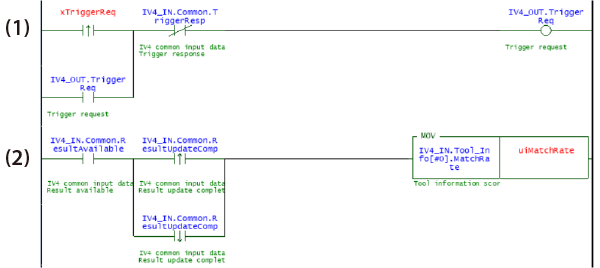
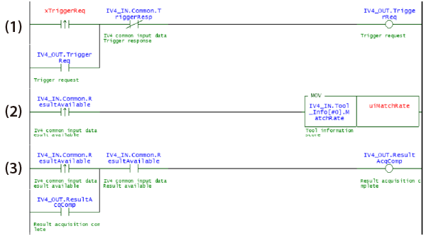
- (1) Turns ON the trigger request, and holds until the trigger response is turned ON.
- (2) Copies the data written to the tool score when the result acquisition possible is turned ON and at the rising or falling of result update completion
One point
Program can be created with a manual-less ladder!
Relay input is possible only by entering some portion of the device comments during entry of operand. (RT edit function)
Time to search for relay numbers is eliminated, leading to the reduction of man hours for program creation.
Reading judgment results (handshaking control enabled)
Mnemonic symbol list
LDP xTriggerReq
OR IV4_OUT.TriggerReq
ANB IV4_IN.Common.TriggerResp
OUT IV4_OUT.TriggerReq
LDP IV4_IN.Common.ResultAvailable
MOV IV4_IN.Tool_Info[#0].MatchRate uiMatchRate
LDP IV4_IN.Common.ResultAvailable
OR IV4_OUT.ResultAcqComp
AND IV4_IN.Common.ResultAvailable
OUT IV4_OUT.ResultAcqComp

- (1) Turns ON the trigger request, and holds until the trigger response is turned ON.
- (2) Copies the data written to the tool score when the result acquisition possible is turned ON.
- (3) Turns ON the result acquisition completion notification when the result acquisition possible is turned ON, and holds until the result acquisition possible is turned OFF.
Switching the program
Mnemonic symbol list
LDP xChangeProgram
MOV uiProgramNo IV4_OUT.ProgramNo
LDP xChangeProgram
OR IV4_OUT.ProgramSwitchReq
ANB IV4_IN.Common.ProgramSwitchResp
OUT IV4_OUT.ProgramSwitchReq

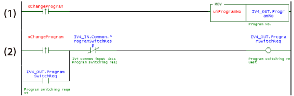
- (1) Writes the program number.
- (2) Turns ON the program switching request, and holds until the program switching response is turned ON.
Changing the judgment threshold of tools
Mnemonic symbol list
LDP xChangeThreshold
MOV uiThresSettingNo IV4_OUT.SettingNo
MOV.D udiThreshold IV4_OUT.SettingVal
LDP xChangeThreshold
OR IV4_OUT.SettingValChgReq
ANB IV4_IN.Common.SetValChgResp
OUT IV4_OUT.SettingValChgReq
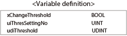
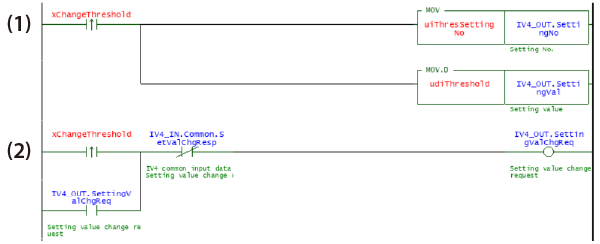
- (1) Writes upper/lower threshold setting numbers*1 and upper/lower thresholds.
- (2) Turns ON the setting value change request, and holds until the setting value change response is turned ON.
- *1Upper/lower threshold setting numbers differ depending on the tool number and the type of threshold.
For details, refer to the IV4 Series User’s Manual.
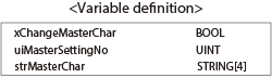
Changing the master text
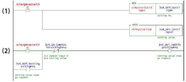
Mnemonic symbol list
LDP xChangeMasterChar
MOV uiMasterSettingNo IV4_OUT.SettingNo
SMOV strMasterChar IV4_OUT.SettingVal
LDP xChangeMasterChar
OR IV4_OUT.SettingValChgReq
ANB IV4_IN.Common.SetValChgResp
OUT IV4_OUT.SettingValChgReq
- (1) Writes the master text setting number*1 and master text.
- (2) Turns ON the setting value change request, and holds until the setting value change response is turned ON.
- *1The setting number differs depending on the tool that changes the master text.
For details, refer to the IV4 Series User’s Manual
One point
The IV4 Series handles character strings using the character code UTF-8.
Since the KV Series handles character strings using the character code Shift JIS, character strings that cannot be expressed with the ASCII code cannot be specified.
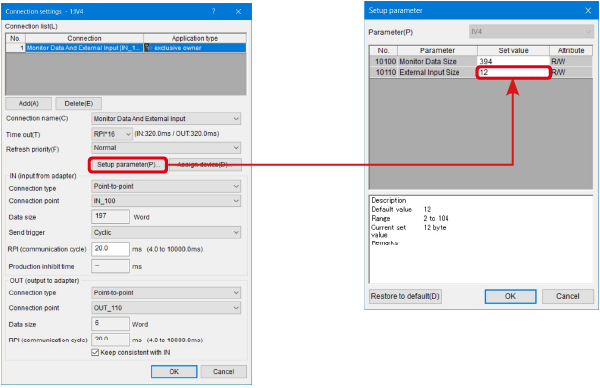
One point
The default connection setting can change only up to 4 master text at a time.
Changing the connection setting allows 5 or more master text to be changed at a time.
Select [Tool (T)] → [Built-in EtherNet settings (E)] → [EtherNet/IP settings (W)], and open the [EtherNet/IP settings] window. On the [EtherNet/ IP settings] window, right-click the IV4 Series icon, and select [Connection setting (N)].
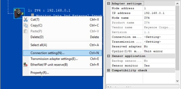
Click "Setup parameter" and increase the "External Input Size" setting value. Then the number of characters that can be changed at a time can be expanded.