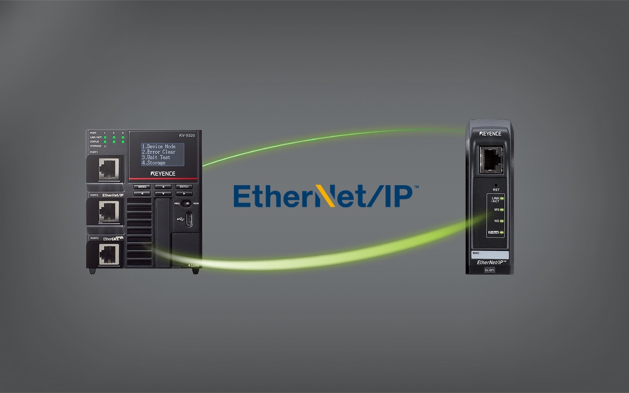
KV-X Series × DL-EP1
EtherNet/IP™ Connection Guide
Return to KV Series Connection Guide
Applicable models
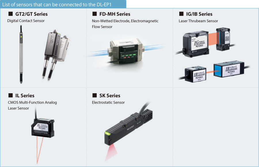
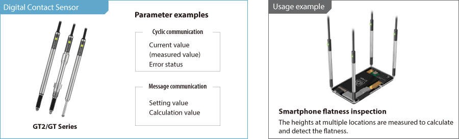
- Digital Contact Sensor GT2/GT Series
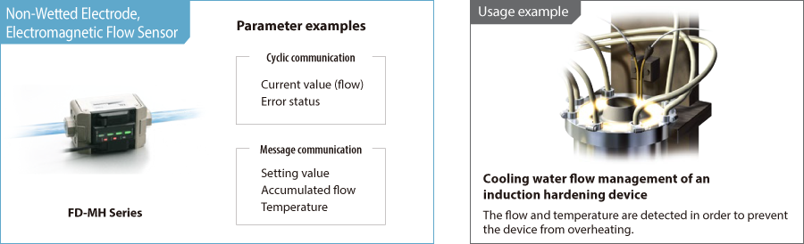
- Non-Wetted Electrode, Electromagnetic Flow Sensor FD-MH Series
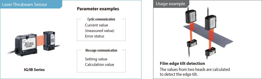
- Laser Thrubeam Sensor IG/IB Series
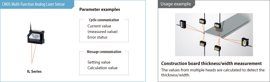
- CMOS Multi-Function Analog Laser Sensor IL Series
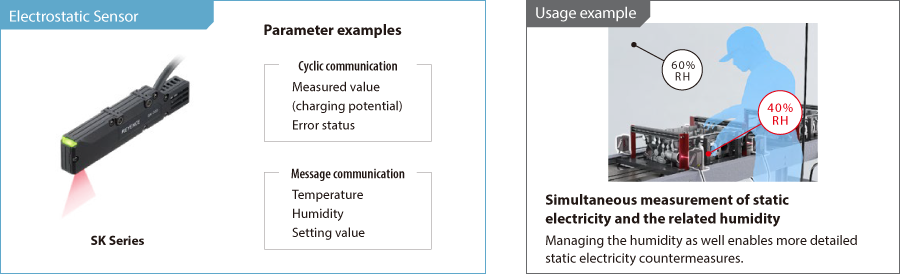
- Electrostatic Sensor SK Series
Contents
Preface 1 : Sensors That Can Be Connected to the DL-EP1
This section introduces models that can be connected to the DL-EP1.
One point
The DL-EP1 can connect to multiple sensors and these sensors can be of different types.
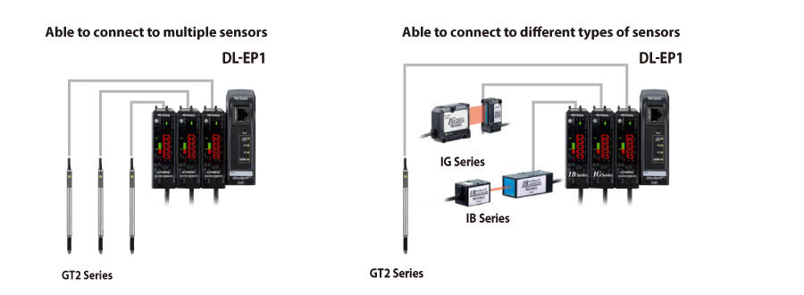
* There are limits on the maximum number of connected units and the type of units that can be connected at the same time.
See “ Extra 1 Precautions When Using Multiple Sensors”.
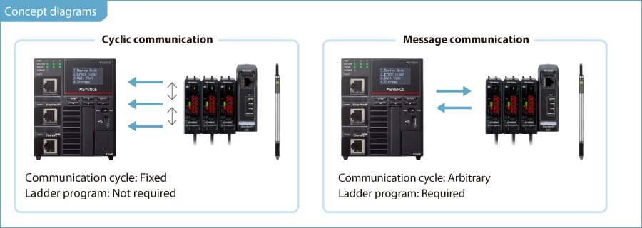
Preface 2 : Communication with the DL-EP1
DL-EP1 communication method
The DL-EP1 uses EtherNet/IP communication to transfer data to the PLC. Two communication methods are supported: cyclic communication, in which
communication is performed at a fixed cycle, and message communication, in which communication is performed with arbitrary timing.
Cyclic communication:
With this function, data is communicated between the KV Series and the DL-EP1 at a fixed cycle. This is used when reading parameters such as current values that are very frequently used.
Message communication:
With this function, commands are executed with arbitrary timing to perform communication. This is used when reading and writing parameters such as setting values that do not require punctuality.
Current value, error status, and output status monitoring → Cyclic communication (see Step 1 to Step 3)
Reading and writing detailed parameters such as setting values → Message communication (see Step 1 to Step 5)
One point
When you set the DL-EP1 (see Step 2 ), cyclic communication starts automatically when the cyclic communication settings are configured. To perform message communication, a ladder program (see Step 4 ) is required in addition to the cyclic communication settings.
To perform cyclic communication ➞ Configure the settings from Step 1 to Step 3.
To perform message communication ➞ Configure the settings from Step 1 to Step 5.
Preface 3 : Typical Parameters of Connected Models
Typical parameters and usage examples
This section introduces typical examples of parameters that can be checked with the cyclic communication and message communication of each sensor.
* For the list of cyclic communication/message communication parameters, see “ Extra 2 Parameter List”.
This document introduces an example of connecting the GT2 Series.
* Substitute references to the GT2 Series with the sensor amplifier that you are connecting.
To perform cyclic communication ➞ Configure the settings from Step 1 to Step 3.
To perform message communication ➞ Configure the settings from Step 1 to Step 5.
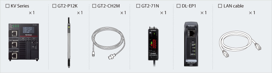
Step 1 : Checking the Equipment Required for Connection
This guide provides a description on communicating with the KV Series as an example.
If you are using a different unit, replace references to the KV Series with the unit that you are using.
Prepare the following equipment.
Step 2 : DL-EP1 Settings
The following two methods are available for setting the configuration of the DL-EP1.
- Set the DL-EP1 automatically from the read sensor amplifier information.
- Set the DL-EP1 by manually selecting the sensor amplifier (see page ”Sensor setting command explanation”).
➾ Use this setup method if you cannot prepare an actual device.
The following pages will explain the procedure to set the DL-EP1 automatically.
1. Open the Unit Editor of KV STUDIO.
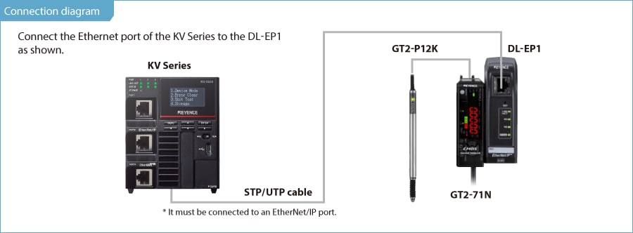
2. On the KV Series A’s [Setup unit(2)] tab, click  for the EtherNet/IP settings.

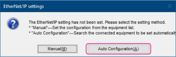
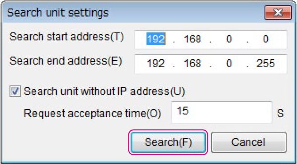
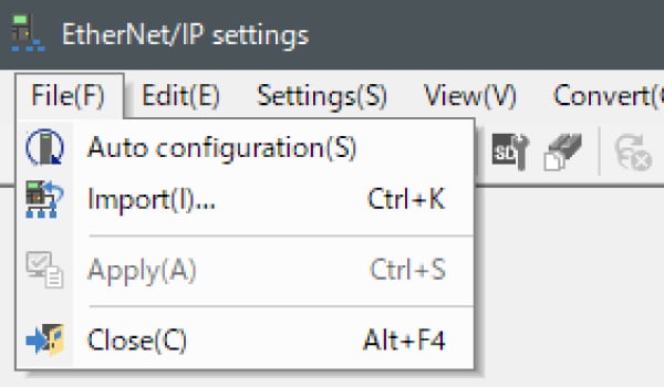
3. The following dialog will be displayed. Click “Auto Configuration (A)”.
One point
The following conditions are required in order to search for the DL-EP1.
- The DL-EP1 and the KV Series must be connected by a LAN cable.
- Both the DL-EP1 and the KV Series must be turned on.
- If you are using an Ethernet switch, the DL-EP1 and KV Series must both be connected to the Ethernet switch with LAN cables, and the Ethernet switch must be turned on.
4. Click [Search(F)].
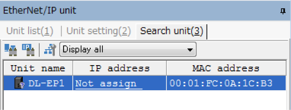
5. The unassigned DL-EP1s that were found are displayed.
One point
To clear the assignment of the DL-EP1 IP address, hold down the RST switch on the face of the DL-EP1 for 3 seconds or more. If multiple DL-EP1s are connected and you do not know which IP address corresponds to which DL-EP1, you can use the MAC address written on the DL-EP1 to differentiate the DL-EP1s.
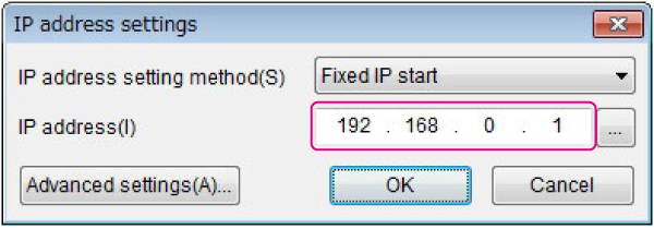
6. Click the IP address, and then set the DL-EP1 IP address to “192.168.0.1” in the [IP address settings] dialog box.
One point
Click in the ![]() [IP address settings] dialog box to search for IP addresses that are not in use.
[IP address settings] dialog box to search for IP addresses that are not in use.
Step 3 : KV-X Series Connection Settings
This section explains how to connect with a fictitious device called "Vendor Series". Replace the "Vender Series" with the device to be connected.
One point
For the KV Series with a CPU function version of 2.0 or later, variables can be assigned to the connection of EtherNet/IP.
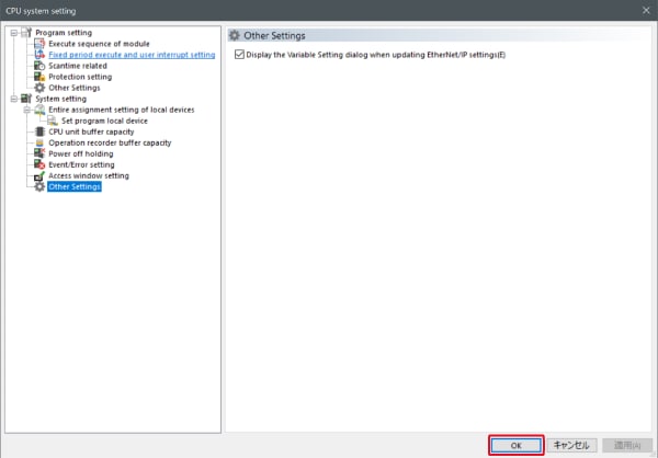
When assigning variables to the connection of EtherNet/IP®, check the box of “Displays the variable setting dialog when updating the EtherNet/IP settings (E)” for “Other settings” of “System settings” on the “CPU system settings” dialog.
The “CPU system settings” dialog is displayed by selecting [Display (V)] ⇒ [CPU system settings (P)] from the ”KV STUDIO” menu.
When the box of "Displays the variable setting dialog when updating the EtherNet/IP settings (E)" is checked, at the timing when the EtherNet/IP setting is updated and the changed content of the unit editor is confirmed, a dialog to assign variables to the connection is displayed.
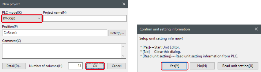
1. Start up the KV STUDIO and create a new project. Set the model option to “KV-X520” and click [OK].
A [Confirm unit configuration setting] dialog box is displayed. Click [Yes (Y)].
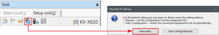
2. The unit editor is displayed. On the “Setup unit(2)” tab, click the icon of EtherNet/IP setting. A configuration type selection dialog box is displayed. Click [Manual (M)].
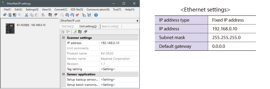
3. On the “Unit setting (2)” tab, set the IP address for KV-X Series. In this example, configure the setting as shown below.
* Step 4 needs to be performed to import a sensor setting file. When the sensor setting file has already been imported, proceed to Step 5.
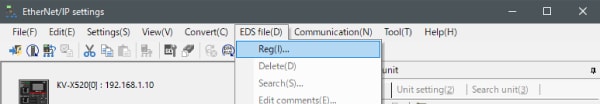
4. Select [EDS file (D)] → [Reg (I)] to import the KEYENCE sensor setting file(ez1 file) or EDS file.
* Download the sensor setting file from the KEYENCE website.
5. With the KV-X Series and the EtherNet/IP devices connected using the Ethernet cable, select [File (F)] → [Auto configuration (S)] on the [EtherNet/IP settings] window.
6. When the configuration on the unit editor differs from that of the actual device, a dialog for confirming transfer of the project is displayed. With the PC and KV-X Series connected using the USB cable, click [Yes (Y)].
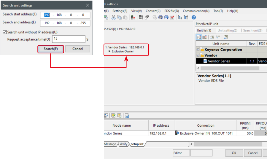
7. When transfer of the project is completed, the [Search unit settings] dialog is displayed. Then click [Search (F)]. After the auto configuration is completed, "Vendor Series" is automatically registered. Then click [OK] to close the [EtherNet/IP settings] window.
8. Click [OK] on the unit editor to exit.
One point
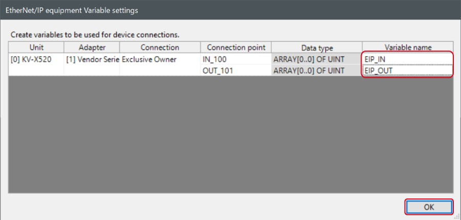
When the box of "Displays the variable setting dialog when updating the EtherNet/IP settings (E)" is checked, the [EtherNet/IP equipment Variable settings] dialog is displayed.
Enter the name of variable assigned to the connection, and click [OK].
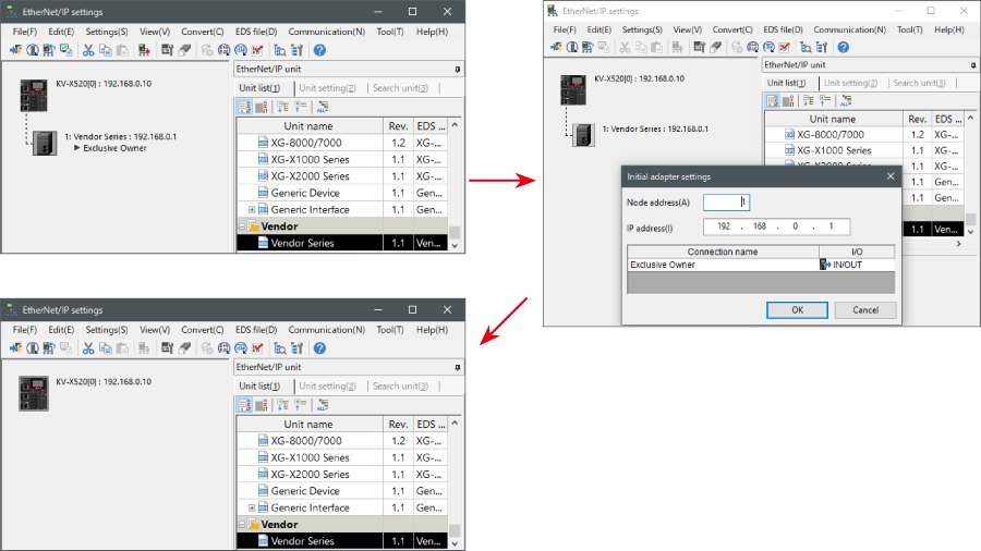
- The way of Device Configuration Settings manually
In the [Unit list (1)] tab of “EtherNet/IP Settings”, drag and drop "Vendor Series" and create a device configuration.
Transferring and Monitoring Setting Data
1. From the menu, select [Monitor/Simulator (N)] > [Transfer to PLC (W) → Monitor mode (C)].
In the [Send comm. cmd. to PLC] dialog box, click [Execute(E)].
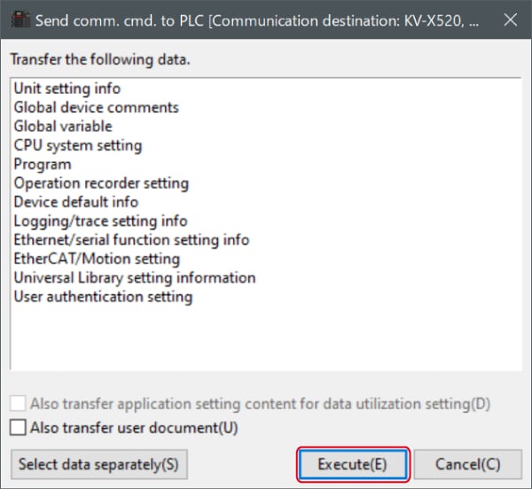
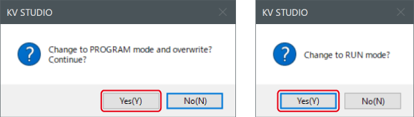
2. If the following dialog box is displayed before and after transferring the data, click [Yes] both times.
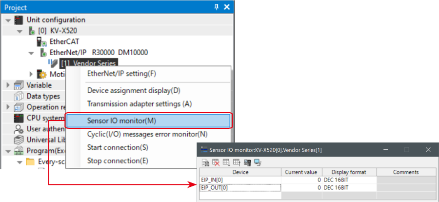
3. Right-click on “Vender Series” in the workspace, and select [Sensor IO monitor (M)].
Scores and other information can be easily monitored.
One point
The information can also be checked on a graph by starting up the real time chart monitor.
Right-click on “Sensor I/O monitor” and select [Real time chart monitor (H)].
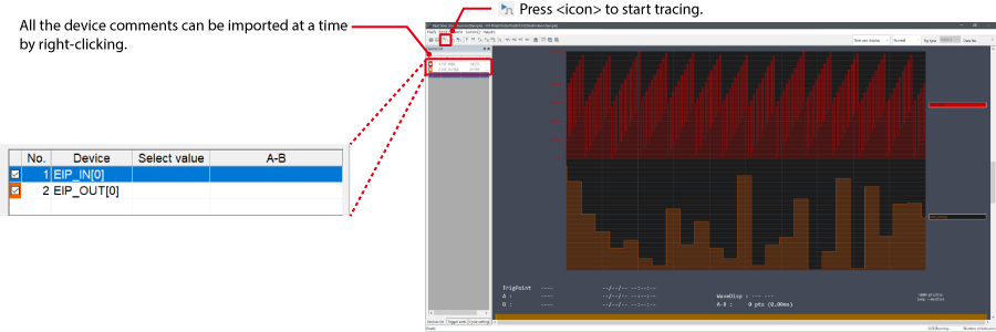
Range adjustment is not required since the real time chart monitor performs scaling automatically.
When Manipulating Parameters with a Program
Changing the Setting Values
The setting values of the sensors can be changed by the following two methods:
A : Change from a PC
B : Change from a ladder program
A : Change from a PC
To change the settings from a PC, use the transmission adapter function in KV STUDIO.
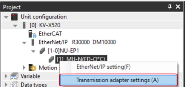
1. Expand the unit configuration in the workspace. Right-click on "Vender Series" and select [Transmission adapter settings (A)].
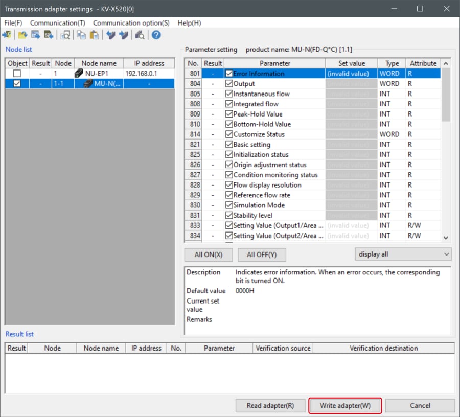
2. Place a check mark in Setting Value for "Vender Series" and enter the setting value.
Click [Write adapter (W)] to write the setting value to the sensor.
*To read the setting value of a sensor, select [Read adapter (R)].
B : Changed from a ladder program
Use message communication to change the setting values from a ladder program.
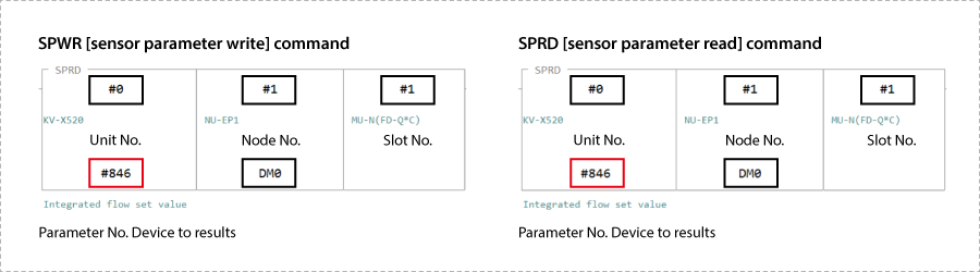
To perform message communication with KV STUDIO, use the sensor setting commands (SPWR [sensor parameter write] and SPRD [sensor parameter read]).
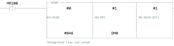
1. In Editor mode, create a ladder program as shown below.
* For the parameter numbers, refer to Parameter list.
2. Transfer the ladder program.
3. When MR100 is turned on, the setting value is changed.
* Store the setting value in DM4 ([Leading device to store results] + 4).
One point
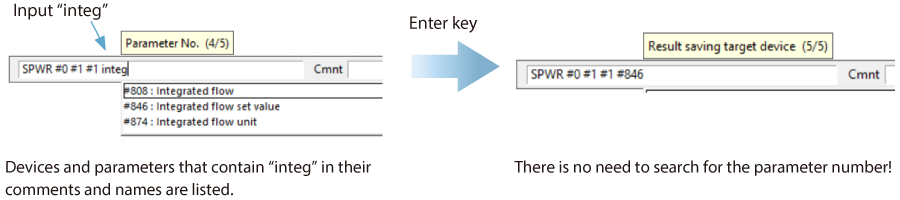
RT (Real-Time) Edit function
When you use a ladder program, you can input device comments or parameter names directly to have input candidates be searched for and displayed automatically.
Step 4 : Message Communication Settings
If you are only reading or writing current values then message communication is not necessary and there is no need to perform the procedure outlined in the Step4~Step5.
1. If you are in monitor mode, switch to editor mode.
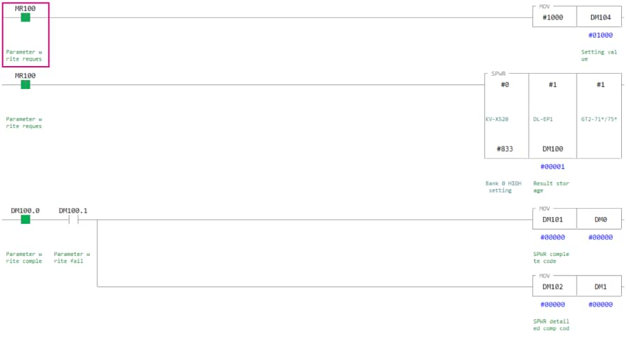
2. Use the SPWR (sensor parameter write) command to write the following ladder program. Example) When MR100 turns on, the GT2 Series HI setting value changes to 1000.
List of mnemonics
LDP MR100
MOV #1000 DM104 LDP MR100
SPWR #0 #1 #1 #833 DM100 LD DM100.0
AND DM100.1 MOV DM101 DM0 MOV DM102 DM1
* For an explanation of the SPWR command, see One point.
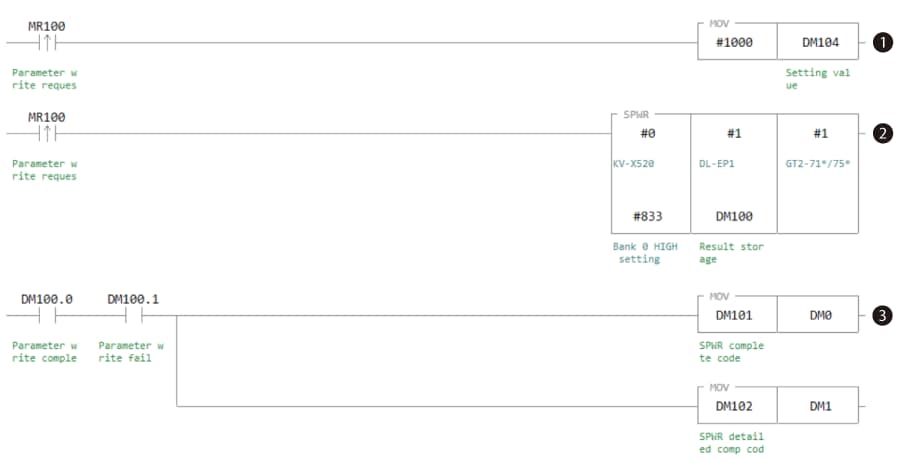
Flow of the above ladder program
➊ Store the value to write (#1000) into the setting value (DM104).
➋ Write the setting value (#1000) into the KV Series (unit number: #0), the node 1 DL-EP1 (node address: #1), the slot 1 GT2-71N (slot number: #1), and the HI setting value (parameter number: #833).
➌ If the execution of the SPWR (sensor parameter write) command fails, the completion code and the detailed completion code are stored in DM0 and DM1.
One point
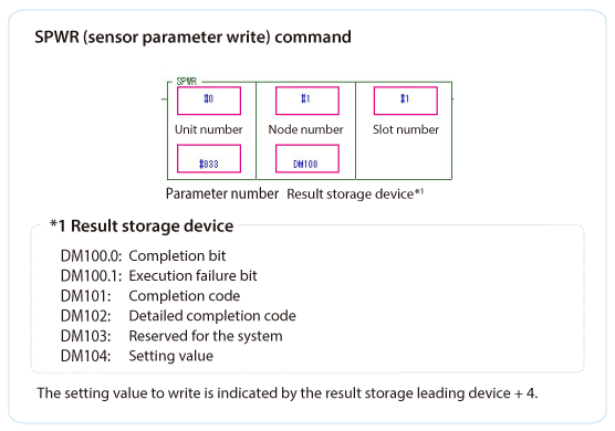
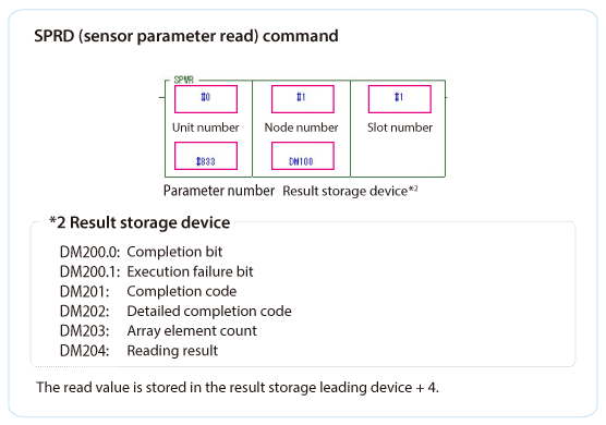
Sensor setting command explanation
If you execute the SPWR (sensor parameter write) command or the SPRD (sensor parameter read) command, the specified sensor parameter is written or read, respectively.
3. Transfer the setting data and then switch to monitor mode. When MR100 is turned on, 1000 is written to the GT2 Series HI setting value.
If DM100.0 (the SPWR completion bit) turns on and DM100.1 (the SPWR execution failure bit) is off after MR100 turns on, the parameter have been written correctly. Also, if the writing operation fails, DM100.1 (the SPWR execution failure bit) turns on, and the completion code and detailed completion code are stored in DM0 and DM1, respectively. (The completion code for normal writing is “0.”)
* For details on the completion codes, see “7-8 Completion Codes” in the “EtherNet/IP Function User’s Manual.”
Step 5 : Checking Values Changed by Message Communication
Message communication can be used to check whether the GT2-71N's HI setting value has been properly set to a value of 1000. The following two methods are available for checking whether the setting value has been applied to the GT2-71N.
➊ Check the GT2-71N sensor amplifier directly.
➋ Use the adapter setting transfer function in KV STUDIO to read the “setting value on the HIGH side of bank 0.”
➊ Check the GT2-71N sensor amplifier directly.
* For details on how to display the HIGH-side setting value on the sensor amplifier, see the GT2 Series manual.
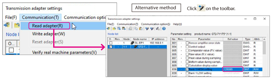
➋ Use the adapter setting transfer function in KV STUDIO to read the “setting value on the HIGH side of bank 0.”
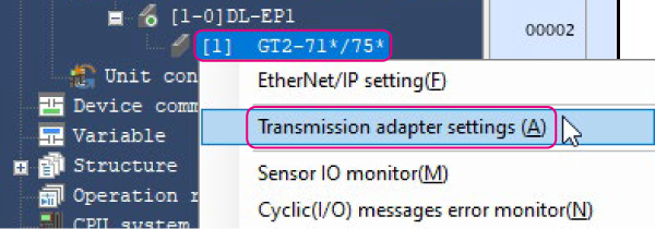
1. Expand the unit configuration in the workspace. Right-click the GT2-71*/75*, and then click [Transmission adapter settings(A)].
2. Select the “Bank 1 HIGH setting” check box for the GT2-71*/75*.
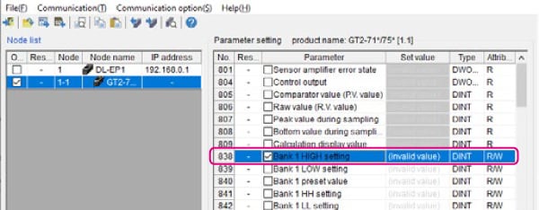
3. On the Transmission adapter settings screen, click [Read adapter(R)] on the [Communication(T)] menu to read the setting value.
Extra 1 : Precautions When Using Multiple Sensors
You can connect the DL-EP1 to multiple sensor amplifiers that are the same or different series.
However, when using multiple sensor amplifiers, you have to pay attention to the maximum number of connected units and to the compatibility between different types of units.
Maximum number of units that can be connected to the DL-EP1
| Name | Maximum number of connected units |
|---|---|
| GT2 | 15 (main unit: 1, expansion units: 14)* |
| GT | 10 (main unit: 1, expansion units: 9) |
| FD-MH | 10 (main unit: 1, expansion units: 9) |
| IG | 4 (main unit: 1, expansion units: 3) |
| IB | 4 (main unit: 1, expansion units: 3) |
| IL | 8 (main unit: 1, expansion units: 7) |
| SK | 8 (main unit: 1, expansion units: 7) |
* Up to 11 sensor heads can be connected to the GT2-100N(P) by expanding 1 main unit with an expansion board.
Compatibility between different types of sensor amplifiers connected to the DL-EP1
| Name | GT2 | GT | FD-MH | IG | IB | IL | SK |
|---|---|---|---|---|---|---|---|
| GT2 | — | ✓ | × | ✓ | ✓ | ✓ | × |
| GT | ✓ | — | × | ✓ | ✓ | ✓ | × |
| FD-MH | × | × | — | × | × | × | × |
| IG | ✓ | ✓ | × | — | ✓ | ✓ | × |
| IB | ✓ | ✓ | × | ✓ | — | ✓ | × |
| IL | ✓ | ✓ | × | ✓ | ✓ | — | × |
| SK | × | × | × | × | × | × | — |
- The “✓” mark indicates that the combination of different types of sensor amplifiers can be connected to the DL-EP1.
- The “×” mark indicates that the combination of different types of sensor amplifiers cannot be connected to the DL-EP1.
* Note that connecting different types of sensor amplifiers may change the functional limitations and the maximum number of connected units. For details, see the DL-EP1 manual or contact your nearest KEYENCE office.
Extra 2 : Parameter List
Parameter lists for the cyclic communication and message communication of the connectable sensors are shown below.
* For details on the parameters, see the sensor amplifier manuals.
Cyclic communication parameter list
| Parameter name | GT2 | GT | IG | IB | IL | FD-MH | SK |
|---|---|---|---|---|---|---|---|
| Status | ✓ | ✓ | ✓ | ✓ | ✓ | ✓ | ✓ |
| Sensor error status | ✓ | ✓ | ✓ | ✓ | ✓ | ✓ | ✓ |
| Sensor warning status | — | — | — | ✓ | ✓ | — | ✓ |
| Current value 0, over range | ✓ | ✓ | ✓ | ✓ | ✓ | ✓ | ✓ |
| Current value 0, under range | ✓ | ✓ | ✓ | ✓ | ✓ | ✓ | ✓ |
| Current value 0, invalid | ✓ | ✓ | ✓ | ✓ | ✓ | ✓ | ✓ |
| Output 1 | ✓ | ✓ | ✓ | ✓ | ✓ | ✓ | ✓ |
| Output 2 | ✓ | ✓ | ✓ | ✓ | ✓ | ✓ | ✓ |
| Output 3 | ✓ | ✓ | ✓ | ✓ | ✓ | ✓ | ✓ |
| Output 4 | ✓ | — | ✓ | ✓ | ✓ | — | ✓ |
| Output 5 | ✓ | — | — | — | — | — | — |
| External input response 1 | ✓ | ✓ | ✓ | ✓ | ✓ | ✓ | ✓ |
| External input response 2 | ✓ | ✓ | ✓ | ✓ | ✓ | — | ✓ |
| External input response 3 | ✓ | ✓ | ✓ | ✓ | ✓ | ✓ | ✓ |
| External input response 4 | ✓ | — | ✓ | ✓ | ✓ | ✓ | ✓ |
| External input response 5 | — | — | ✓ | — | — | — | — |
| Error ID number | ✓ | ✓ | ✓ | ✓ | ✓ | ✓ | ✓ |
| Error code | ✓ | ✓ | ✓ | ✓ | ✓ | ✓ | ✓ |
| Warning ID number | — | — | — | ✓ | ✓ | — | ✓ |
| Warning code | — | — | — | ✓ | ✓ | — | ✓ |
| Current value 0 | ✓ | ✓ | ✓ | ✓ | ✓ | ✓ | ✓ |
Message communication parameter list
| Parameter name | Parameter number | GT2 | GT | IG | IB | IL | FD-MH | SK |
|---|---|---|---|---|---|---|---|---|
| Status | #100 | ✓ | ✓ | ✓ | ✓ | ✓ | ✓ | ✓ |
| Error status | #101 | ✓ | ✓ | ✓ | ✓ | ✓ | ✓ | ✓ |
| Warning status | #102 | — | — | — | ✓ | — | — | — |
| Current value 0 property | #104 | ✓ | ✓ | ✓ | ✓ | ✓ | ✓ | ✓ |
| Current value 1 property | #105 | ✓ | ✓ | — | — | — | — | — |
| Error ID number | #108 | ✓ | ✓ | ✓ | ✓ | ✓ | ✓ | ✓ |
| Error code | #109 | ✓ | ✓ | ✓ | ✓ | ✓ | ✓ | ✓ |
| Warning ID number | #110 | — | — | — | ✓ | — | — | — |
| Warning code | #111 | — | — | — | ✓ | — | — | — |
| Output 1 | #116 |
✓ (HIGH output) |
✓ (HIGH output) |
✓ (HIGH output) |
✓ (HIGH output) |
✓ (HIGH output) |
✓ | ✓ |
| Output 2 | #117 |
✓ (LOW output) |
✓ (LOW output) |
✓ (LOW output) |
✓ (LOW output) |
✓ (LOW output) |
✓ | ✓ |
| Output 3 | #118 |
✓ (GO output) |
✓ (GO output) |
✓ (GO output) |
✓ (GO output) |
✓ (GO output) |
✓ | ✓ |
| Output 4 | #119 |
✓ (HH output) |
— |
✓
(Edge check output) |
✓
(Edge check output) |
✓
(Edge check output) |
— | ✓ |
| Output 5 | #120 |
✓ (LL output) |
— | — | — | — | — | — |
| Current value 0, etc., invalid | #138 | ✓ | ✓ | ✓ | ✓ | ✓ | ✓ | ✓ |
| Current value 0, etc., under range | #139 | ✓ | ✓ | ✓ | ✓ | ✓ | ✓ | ✓ |
| Current value 0, etc., over range | #140 | ✓ | ✓ | ✓ | ✓ | ✓ | ✓ | ✓ |
| Current value 0 (ID numbers 1 to 15) | #144 to #158 | ✓ | ✓ | ✓ | ✓ | ✓ | ✓ | ✓ |
| Sensor status master setting | #176 | ✓ | ✓ | ✓ | ✓ | ✓ | ✓ | ✓ |
| Number of connected sensors | #177 | ✓ | ✓ | ✓ | ✓ | ✓ | ✓ | ✓ |
| Error code (ID numbers 00 to 15) | #768 to #783 | ✓ | ✓ | ✓ | ✓ | ✓ | ✓ | ✓ |
| Sensor amplifier error status | #801 | ✓ | ✓ | ✓ | — | ✓ | ✓ | ✓ |
| Control output | #804 | ✓ | ✓ | — | — | — | — | — |
| Judgment value (P.V. value) | #805 | ✓ | ✓ | ✓ | ✓ | ✓ | — | ✓ |
| Current value (R.V. value) | #806 | ✓ | ✓ | — | — | — | — | — |
| Peak hold value in P-P mode | #807 | ✓ | — | — | — | — | — | — |
| Bottom hold value in P-P mode | #808 | ✓ | — | — | — | — | — | — |
| Calculation display value | #809 | ✓ | ✓ | — | — | — | — | — |
| Peak value during sampling interval | #807 | — | ✓ | — | — | — | — | — |
| Bottom value during sampling interval | #808 | — | ✓ | — | — | — | — | — |
| Judgment output / edge check output | #804 | — | — | ✓ | — | — | — | — |
| Internal measured value (R.V. value) | #806 | — | — | ✓ | ✓ | ✓ | — | ✓ |
| Peak hold value during hold | #807 | — | — | ✓ | ✓ | ✓ | — | ✓ |
| Bottom hold value during hold | #808 | — | — | ✓ | ✓ | ✓ | — | ✓ |
| Calculated value (CALC value) | #809 | — | — | ✓ | — | ✓ | — | — |
| Analog output value | #810 | — | — | ✓ | ✓ | ✓ | — | — |
| Number of edges | #813 | — | — | ✓ | — | — | — | — |
| Optical-axis alignment status | #814 | — | — | ✓ | — | — | — | — |
| Setting error | #819 | — | — | ✓ | ✓ | ✓ | — | ✓ |
| EEPROM write result | #821 | — | — | ✓ | ✓ | ✓ | — | ✓ |
| Zero shift execution result | #822 | — | — | ✓ | ✓ | ✓ | — | — |
| Reset execution result | #823 | — | — | ✓ | ✓ | ✓ | — | ✓ |
| System parameter current status | #824 | — | — | ✓ | ✓ | ✓ | — | ✓ |
| Reference waveform registration request result | #826 | — | — | ✓ | — | — | — | — |
| Tolerance/two-point tuning execution result | #828 | — | — | ✓ | — | — | — | — |
| Calibration execution result | #829 | — | — | ✓ | — | ✓ | — | — |
| Judgment output / alarm output | #804 | — | — | — | — | ✓ | — | ✓ |
| Error status | #801 | — | — | — | ✓ | ✓ | — | — |
| Warning status (check output status) | #802 | — | — | — | ✓ | — | — | — |
| Warning function operation status (check output function operation status) | #803 | — | — | — | ✓ | ✓ | — | — |
| Judgment output / check output | #804 | — | — | — | ✓ | — | — | — |
| Bank status | #811 | — | — | — | ✓ | ✓ | — | ✓ |
| Timing status | #812 | — | — | — | ✓ | ✓ | — | ✓ |
| Laser emission stop status | #818 | — | — | — | ✓ | ✓ | — | — |
| External input status | #820 | — | — | — | ✓ | ✓ | ✓ | ✓ |
| Reference light intensity registration result | #826 | — | — | — | ✓ | — | — | — |
| Adjustment execution result | #827 | — | — | — | ✓ | — | — | — |
| Tuning execution result | #828 | — | — | — | ✓ | ✓ | — | — |
| Execution result | #829 | — | — | — | ✓ | — | — | — |
| Control output, accumulation pulse output, or error alarm output status | #804 | — | — | — | — | — | ✓ | — |
| Instantaneous flow value | #805 | — | — | — | — | — | ✓ | — |
| Accumulated flow value | #806 | — | — | — | — | — | ✓ | — |
| Instantaneous flow (peak hold value) | #807 | — | — | — | — | — | ✓ | — |
| Instantaneous flow (bottom hold value) | #808 | — | — | — | — | — | ✓ | — |
| Bank switching status | #811 | — | — | — | — | — | ✓ | — |
| Current temperature | #813 | — | — | — | — | — | ✓ | — |
| Temperature peak hold value | #814 | — | — | — | — | — | ✓ | — |
| Temperature bottom hold value | #815 | — | — | — | — | — | ✓ | — |
| Temperature sensor connection | #822 | — | — | — | — | — | ✓ | — |
| Output status | #804 | — | — | — | — | — | — | — |
| Instantaneous density | #816 | — | — | — | — | — | — | — |
| Shift processing result | #822 | — | — | — | — | — | — | — |
| Bank 0, etc. HIGH-side setting value | #833, etc. | ✓ (+ 5 × n)* | ✓ (+ 3 × n) | — | — | — | — | — |
| Bank 0, etc. LOW-side setting value | #834, etc. | ✓ (+ 5 × n) | ✓ (+ 3 × n) | — | — | — | — | — |
| Bank 0, etc. preset value | #835, etc. | ✓ (+ 5 × n) | ✓ (+ 3 × n) | — | — | — | — | — |
| Bank 0, etc. HH-side setting value | #836, etc. | ✓ (+ 5 × n) | — | — | — | — | — | — |
| Bank 0, etc. LL-side setting value | #837, etc. | ✓ (+ 5 × n) | — | — | — | — | — | — |
| HIGH-side setting value (bank 0, etc.) | #833, etc. | — | — | ✓ (+ 6 × n) | ✓ (+ 3 × n) | ✓ | — | — |
| LOW-side setting value (bank 0, etc.) | #834, etc. | — | — | ✓ (+ 6 × n) | ✓ (+ 3 × n) | ✓ | — | — |
| Shift target value (bank 0, etc.) | #835, etc. | — | — | ✓ (+ 6 × n) | ✓ (+ 3 × n) | ✓ | — | — |
| Sensitivity setting (bank 0, etc.) | #836, etc. | — | — | ✓ (+ 6 × n) | — | — | — | — |
| User-defined binarization (bank 0) | #837, etc. | — | — | ✓ (+ 6 × n) | — | — | — | — |
| User-defined filter value (bank 0, etc.) | #838 | — | — | ✓ | — | — | — | — |
| Instantaneous flow values 1 and 2 | #833 and #834 | — | — | — | — | — | ✓ | — |
| Temperature upper limit setting value | #835 | — | — | — | — | — | ✓ | — |
| Temperature lower limit setting value | #836 | — | — | — | — | — | ✓ | — |
| Accumulated flow setting values 1 to 4 | #837 to #840 | — | — | — | — | — | ✓ | — |
| Specified density for voLS | #842 | — | — | — | — | — | — | — |
| Analog output upper limit value (bank 0, etc.) | #836 | — | — | — | — | ✓ | — | — |
| Analog output lower limit value (bank 0, etc.) | #837 | — | — | — | — | ✓ | — | — |
| Key lock | #865 | ✓ | ✓ | ✓ | — | ✓ | — | — |
| Bank selection status | #866 | ✓ | ✓ | ✓ | ✓ | — | — | — |
| Timing status | #867 | ✓ | ✓ | — | — | — | — | — |
| Bar display mode | #871 | ✓ | ✓ | — | — | — | — | — |
| Timing input request | #867 | — | — | ✓ | — | — | — | — |
| Laser emission stop input request | #868 | — | — | ✓ | — | — | — | — |
| Display screen of the sub-display unit | #872 | — | — | ✓ | ✓ | ✓ | — | ✓ |
| System parameter | #873 | — | — | ✓ | ✓ | ✓ | — | ✓ |
| Tolerance tuning, tolerance setting width | #874 | — | — | ✓ | ✓ | ✓ | — | — |
| Calibration function | #875 | — | — | ✓ | ✓ | ✓ | — | — |
| Calibration function set 1, etc. | #876, etc. | — | — | ✓ | — | ✓ | — | — |
| Edge number 1 (bank 0, etc.) | #884, etc. | — | — | ✓ (+ 3 × n) | — | — | — | — |
| Edge number 2 (bank 0, etc.) | #885 | — | — | ✓ (+ 3 × n) | — | — | — | — |
| Number of pins (bank 0, etc.) | #886, etc. | — | — | ✓ (+ 3 × n) | — | — | — | — |
| Key lock setting | #865 | — | — | — | ✓ | — | — | — |
| Bank function | #866 | — | — | — | — | ✓ | — | ✓ |
| Timing input | #867 | — | — | — | ✓ | ✓ | — | ✓ |
| Laser emission stop input | #868 | — | — | — | ✓ | ✓ | — | — |
|
Actual measurement correction/theoretical
correction point 1 target value |
#876 | — | — | — | ✓ | — | — | — |
|
Actual measurement correction/theoretical
correction point 2 target value |
#877 | — | — | — | ✓ | — | — | — |
| Theoretical correction point 1 measured value | #883 | — | — | — | ✓ | — | — | — |
| Theoretical correction point 2 measured value | #884 | — | — | — | ✓ | — | — | — |
| Key lock function | #865 | — | — | — | — | — | ✓ | ✓ |
| Analog output selection | #867 | — | — | — | — | — | ✓ | — |
| Free range analog upper limit value | #868 | — | — | — | — | — | ✓ | — |
| Free range analog lower limit value | #869 | — | — | — | — | — | ✓ | — |
| Key lock function | #865 | — | — | — | — | — | — | — |
| Calculation mode / calculation setting | #897 | ✓ | — | — | — | — | — | — |
| Detection mode | #898 | ✓ | ✓ | — | — | — | ✓ | — |
| Hold update method | #899 | ✓ | — | — | — | — | — | — |
| Response time | #900 | ✓ | ✓ | — | — | — | ✓ | — |
| Timing classification | #901 | ✓ | ✓ | — | — | — | — | — |
| Self-timing level | #902 | ✓ | ✓ | — | — | — | — | — |
| Self-timing delay classification | #903 | ✓ | ✓ | — | — | — | — | — |
| User-defined delay time | #904 | ✓ | ✓ | — | — | — | — | — |
| Static hold stability judgment | #905 | ✓ | — | — | — | — | — | — |
| Static hold stability width | #906 | ✓ | — | — | — | — | — | — |
| Measurement fluctuation direction | #907 | ✓ | ✓ | — | — | — | — | — |
| Leverage | #908 | ✓ | ✓ | — | — | — | — | — |
| Output pattern | #909 | ✓ | ✓ | — | — | — | — | — |
| Number of display digits | #910 | ✓ | ✓ | — | — | — | — | — |
| Hysteresis | #911 | ✓ | ✓ | — | — | — | ✓ | — |
| Batch input setting | #912 | ✓ | — | — | — | — | — | — |
| Special output setting | #913 | ✓ | — | — | — | — | — | — |
| Limit output, HH-side judgment position setting | #914 | ✓ | — | — | — | — | — | — |
| Limit output, HH-side judgment position setting | #915 | ✓ | — | — | — | — | — | — |
| Preset data selection | #916 | ✓ | — | — | — | — | — | — |
| Preset record | #917 | ✓ | ✓ | — | — | — | — | — |
| Preset point | #918 | ✓ | — | — | — | — | — | — |
| Power-saving function (ECO) | #919 | ✓ | ✓ | — | — | — | — | — |
| Core alarm | #920 | ✓ | ✓ | — | — | — | — | — |
| Core alarm operation position | #921 | ✓ | — | — | — | — | — | — |
| Batch configuration | #922 | ✓ | — | — | — | — | — | — |
| Analog range setting | #923 | ✓ | — | — | — | — | — | — |
| Free-range setting (Hi side) | #924 | ✓ | — | — | — | — | — | — |
| Free-range setting (Lo side) | #925 | ✓ | — | — | — | — | — | — |
| Calculation mode | #897 | — | ✓ | — | — | — | — | — |
| Delay stability judgment | #905 | — | ✓ | — | — | — | — | — |
| Delay stability width | #906 | — | ✓ | — | — | — | — | — |
| Input (purple wire) function selection 1 | #912 | — | ✓ | — | — | — | — | — |
| Input (pink/purple wire) function selection 2 | #913 | — | ✓ | — | — | — | — | — |
| Checkpoint setting | #921 | — | ✓ | — | — | — | — | — |
| Display filter function | #922 | — | ✓ | — | — | — | — | — |
| Calculation function | #897 | — | — | ✓ | — | ✓ | — | — |
| Measurement mode | #898 | — | — | ✓ | ✓ | — | — | — |
| Measurement direction | #899 | — | — | ✓ | — | ✓ | — | — |
| Sampling rate | #900 | — | — | — | — | ✓ | — | — |
| Averaging count | #901 | — | — | ✓ | — | — | — | ✓ |
| Output pattern | #902 | — | — | ✓ | ✓ | ✓ | — | ✓ |
| Hold function setting | #904 | — | — | ✓ | ✓ | ✓ | — | ✓ |
| Auto-hold trigger level | #905 | — | — | ✓ | ✓ | ✓ | — | — |
| Timing input | #906 | — | — | ✓ | ✓ | ✓ | — | — |
| Delay timer | #907 | — | — | ✓ | ✓ | ✓ | — | — |
| Timer time | #908 | — | — | ✓ | ✓ | ✓ | — | — |
| Hysteresis | #909 | — | — | ✓ | ✓ | ✓ | — | ✓ |
| Analog output scaling | #910 | — | — | ✓ | ✓ | ✓ | — | ✓ |
| Analog output upper limit value | #911 | — | — | ✓ | ✓ | ✓ | — | ✓ |
| Analog output lower limit value | #912 | — | — | ✓ | ✓ | ✓ | — | ✓ |
| External input | #913 | — | — | ✓ | — | ✓ | — | ✓ |
| External inputs 1 to 4 | #914 to #917 | — | — | ✓ | — | ✓ | — | ✓ |
| Reference waveform recording function | #919 | — | — | ✓ | — | — | — | — |
| Zero shift value recording function | #920 | — | — | ✓ | — | ✓ | — | ✓ |
| Mutual interference prevention function | #921 | — | — | ✓ | — | ✓ | — | — |
| Number of display digits | #922 | — | — | ✓ | ✓ | ✓ | — | ✓ |
| Power-saving mode | #923 | — | — | ✓ | ✓ | ✓ | — | — |
| Position monitor | #924 | — | — | ✓ | — | — | — | — |
| Display color | #925 | — | — | ✓ | — | ✓ | — | — |
| Edge check function | #926 | — | — | ✓ | — | — | — | — |
| Edge check function, number of edges | #927 | — | — | ✓ | — | — | — | — |
| Light intensity/attenuation mode | #899 | — | — | — | ✓ | — | — | — |
| Averaging count / high pass filter | #901 | — | — | — | ✓ | — | — | — |
| External input setting | #913 | — | — | — | ✓ | — | — | — |
| External inputs 1 to 4, function selection | #914 to #917 | — | — | — | ✓ | — | — | — |
| Bank switching method | #918 | — | — | — | ✓ | ✓ | — | — |
| Zero shift status saving | #920 | — | — | — | ✓ | — | — | — |
| Judgment output display color | #925 | — | — | — | ✓ | — | — | — |
| P.V. value display color | #926 | — | — | — | ✓ | — | — | — |
| Display averaging | #901 | — | — | — | — | — | ✓ | — |
| Output 2 timeout time | #902 | — | — | — | — | — | ✓ | — |
| Accumulation direction | #903 | — | — | — | — | — | ✓ | — |
| Accumulated flow unit | #904 | — | — | — | — | — | ✓ | — |
| N.O. / N.C. | #909 | — | — | — | — | — | ✓ | — |
| Display mode | #910 | — | — | — | — | — | ✓ | — |
| Bank switching function | #912 | — | — | — | — | — | ✓ | — |
| Zero flow function | #914 | — | — | — | — | — | ✓ | — |
| Alternate frequency mode | #916 | — | — | — | — | — | ✓ | — |
| Power saving mode | #919 | — | — | — | — | — | ✓ | — |
| Flow indicator display color | #925 | — | — | — | — | — | ✓ | — |
| Zero cut level | #905 | — | — | — | — | — | — | — |
| Function for zero cutting when density decreases | #906 | — | — | — | — | — | — | — |
| Zero cut level when density decreases | #907 | — | — | — | — | — | — | — |
| External input function | #912 | — | — | — | — | — | — | — |
| Averaging count / step count filter / high pass filter | #901 | — | — | — | — | ✓ | — | — |
| Head display mode | #924 | — | — | — | — | ✓ | — | — |
| One-shot output time of the step count filter | #926 | — | — | — | — | ✓ | — | — |
| High pass filter cutoff frequency | #927 | — | — | — | — | ✓ | — | — |
| Alarm setting | #929 | — | — | — | — | ✓ | — | — |
| Alarm count | #930 | — | — | — | — | ✓ | — | — |
| Current value to base the calculation on (ID numbers 1 to 15) | #929 to #943 | ✓ | ✓ | — | — | — | — | — |
| Pin diameter/pin interval 1 to 14, P.V. value | #929 to #942 | — | — | ✓ | — | — | — | — |
| Pin diameter/pin interval 1 to 14, R.V. value | #943 to #956 | — | — | ✓ | — | — | — | — |
| Adjustment status saving | #929 | — | — | — | ✓ | — | — | — |
| Adjustment level | #930 | — | — | — | ✓ | — | — | — |
| Auto-adjust function | #931 | — | — | — | ✓ | — | — | — |
| Auto-adjust level | #932 | — | — | — | ✓ | — | — | — |
| Check output function | #933 | — | — | — | ✓ | — | — | — |
| Check output light intensity level | #934 | — | — | — | ✓ | — | — | — |
| Error output mode | #935 | — | — | — | ✓ | — | — | — |
| Trigger level hysteresis | #936 | — | — | — | ✓ | — | — | — |
| Trigger level hysteresis setting value | #937 | — | — | — | ✓ | — | — | — |
| Dry pipe error sensitivity | #929 | — | — | — | — | — | ✓ | — |
| Dry pipe error detection time | #930 | — | — | — | — | — | ✓ | — |
| Flow direction | #931 | — | — | — | — | — | — | — |
| Volume/weight/flow selection | #935 | — | — | — | — | — | — | — |
| Focus specification | #936 | — | — | — | — | — | — | — |
| Model name | #968 | ✓ | ✓ | ✓ | ✓ | ✓ | ✓ | ✓ |
| Sensor head connected by a T-connector | #963 | — | — | ✓ | — | — | — | — |
| Sensor head connected by an R-connector | #964 | — | — | ✓ | — | — | — | — |
| Transmitter-side head model | #963 | — | — | — | ✓ | — | — | — |
| Receiver-side head model | #964 | — | — | — | ✓ | — | — | — |
| Connected sensor head | #963 | — | — | — | — | — | ✓ | — |
| Connected head (capacity) | #963 | — | — | — | — | — | — | — |
| Connected head (material) | #964 | — | — | — | — | — | — | — |
| Temperature | #813 | — | — | — | — | — | — | ✓ |
| Humidity | #814 | — | — | — | — | — | — | ✓ |
| Zero shift/zero shift reset execution result | #822 | — | — | — | — | — | — | ✓ |
| HI-side setting value (bank 0, etc.) | #833, etc. | — | — | — | — | — | — | ✓ (+ 5 × n) |
| LO-side setting value (bank 0, etc.) | #834, etc. | — | — | — | — | — | — | ✓ (+ 5 × n) |
| Range setting | #898 | — | — | — | — | — | — | ✓ |
| Timing input setting | #906 | — | — | — | — | — | — | ✓ |
| Bank switching method | #918 | — | — | — | — | — | — | ✓ |
| Distance correction method | #929 | — | — | — | — | — | — | ✓ |
| Near-side distance correction amount | #930 | — | — | — | — | — | — | ✓ |
| Far-side distance correction amount | #931 | — | — | — | — | — | — | ✓ |
| Area scaling | #932 | — | — | — | — | — | — | ✓ |
| Product code | #961 | — | — | — | — | — | — | ✓ |
| Revision | #962 | — | — | — | — | — | — | ✓ |
| Connected sensor head | #963 | — | — | — | — | — | — | ✓ |
| Series code | #983 | — | — | — | — | — | — | ✓ |
| Series version | #984 | — | — | — | — | — | — | ✓ |
| Device type | #985 | — | — | — | — | — | — | ✓ |
* n: Bank number; leading number of parameter number + 5 × n
