Dimensional Measurement of Positioning and Welding Jigs

The dimensional accuracy of positioning and welding jigs greatly affects the machining accuracy of products manufactured with these jigs. The positions and dimensions of positioning and welding jigs are usually measured with hand tools, such as dial gauges and tape measures, and the three-dimensional shapes are measured with arm coordinate measuring machines (CMMs). These measuring instruments are selected according to the points to be measured and sufficient care must be taken to meet requirements, such as larger jig measurement and quicker construction while maintaining dimensional accuracy.
This section focuses on basic knowledge of positioning and welding jigs required for measuring these jigs and on efficiency improvement of dimensional measurement of these jigs, which greatly affects machining accuracy. The necessity of dimensional measurement of positioning and welding jigs and measurement points are explained and efficiency improvement examples of these measurements are introduced.
- What Is a Jig?
- Roles of Positioning and Welding Jigs
- Necessity for Dimensional Measurement of Positioning and Welding Jigs
- Dimensional Measurement of Positioning and Welding Jigs
- Problems of Dimensional Measurement of Positioning Jigs and Welding Jigs and Their Solutions
- Optimization of Dimensional Measurement of Positioning and Welding Jigs
What Is a Jig?
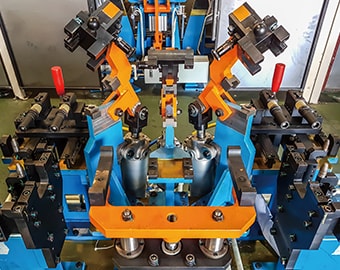
Jigs are tools used to fix products (workpieces) and support manufacturing in processes such as machining, assembly, and inspection. Jigs position and fix products in place, allowing for machining along guides, inspection of machining accuracy, saving of labor and power to reduce costs, improve productivity, reduce human error, and automate manufacturing using robots and automatic equipment.
Jigs are roughly divided into two types: jigs used to guide machining by fixing target products in place and jigs used to fix products in place on machine tools during machining.
Jigs not only help make work processes more efficient by fixing products in place, but also play indispensable roles in automated work using robots and automatic equipment.
Roles of Positioning and Welding Jigs
Various types of jigs are available to suit various uses. For example, positioning jigs are used to position products (workpieces). If a product is accurately fixed in a predetermined position using positioning jigs, it can be machined, such as cutting, polishing, and welding, with automatic equipment. One type of positioning jig is welding jigs, which allow for welding using welding robots and automatic welding machines.
This section introduces the functions of positioning jigs and especially welding jigs that are indispensable for welding automation.
Positioning jig
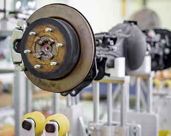
Positioning jigs, also known as fixing jigs or assembly jigs, secure products in predetermined positions for assembly and machining. Fixing jigs, which literally fix products in place, include vises, clamps, and bushings. These jigs position products to support processing using tools such as cutting and grinding.
In addition to jigs used for cutting and grinding, there are also cutting jigs that are used to cut materials into predetermined sizes, insertion jigs that are used to insert parts into predetermined positions, and coating jigs that are used to protect areas to which coatings should not be applied.
All these jigs are used to help reduce machining time, improve machining accuracy, and produce quality that is independent of operator skills as well as save labor and power to reduce costs and allow for automation of manufacturing using robots and automatic equipment.
Welding jig
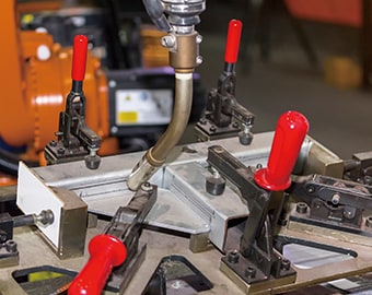
Jigs that fix welding target products are called welding jigs. Welding jigs fix base metals at predetermined positions to ensure accurate welding.
These jigs secure products during welding to support welding work and improve welding techniques, allowing anyone to weld products to predetermined shapes regardless of individual skill. Welding jigs are particularly important for robot welding and automatic welding, in which welding torches are operated and moved to welding positions along specified guides.
Various welding jigs are available according to the welding method. For example, when arc welding is performed automatically, the positions and number of jigs, such as clamps, used for tack welding are different from those used for the final welding. Additionally, when spot welding is performed automatically, the positions and number of jigs need to be carefully determined so that the spot welding gun can reach welding areas.
Necessity for Dimensional Measurement of Positioning and Welding Jigs
Positioning and welding jigs manufactured with high accuracy provide many benefits for machining and inspection processes that use them. However, if the dimensional and installation accuracy of jigs is low, it will have the opposite effect. Additionally, the dimensions of jigs gradually change during manufacturing due to various factors, such as the weight of products (workpieces) and the load of machining, which causes variations in the reference surfaces and the reference 3D coordinates of products.
It is important to measure the dimensions and installation positions of jigs to avoid these problems. The parallelism and perpendicularity of machine tools also change over time, but their machining accuracy can be maintained by measuring these elements and adjusting them using jigs. It is essential to measure the dimensions of jigs during installation and maintenance after installation as well as the dimensions before installation.
Dimensional Measurement of Positioning and Welding Jigs
This section introduces points to note when measuring the dimensions of positioning and welding jigs.
Measurement point
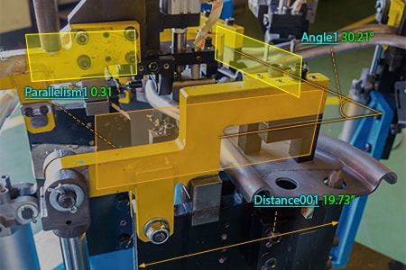
The positioning accuracy of jigs directly affects the accuracy of machining and assembly, so the flatness and parallelism of fixed jigs are important measurement points. For welding jigs, the accuracy of XYZ coordinates is important.
Flatness and parallelism measurement of positioning jigs
When positioning jigs are used for products that are pushed during machining, such as cutting and pressing, products can be positioned stably by placing positioning jigs on the side where the machining load is received. For example, if the flatness and parallelism of reference XY coordinates are not accurate, products positioned in the X and Y directions will be unstable due to unnecessary turning force generated by machining pressure. To prevent this, the jigs need a clamping force that is larger than the turning force, but that large clamping force may reduce the machining accuracy. The machining accuracy will also be reduced if the position accuracy of reference XY coordinates is low, which makes flatness and parallelism of reference coordinates important measurement points.
Accuracy of the XYZ coordinates of welding jigs
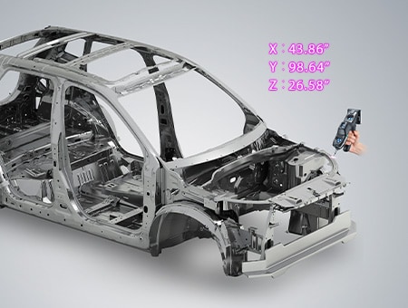
Functions required for welding jigs include fixing of products in place and fixing of them at specified angles. However, high pressures are applied to products during welding. Welding jigs need to be positioned on the X-, Y-, and Z-axes with machining pressure taken into account. If the accuracy of welded products is low, the position accuracy of the XYZ coordinates needs to be improved by processing and adjusting the base, brackets, and positioning pins of the jigs.
A lot of work is also required to correct inaccurate welding of welded products. For these reasons, the position accuracy of welding jig coordinates is an important measurement point because it affects not only the welding process but also work efficiency of post-welding processes.
Problems of Dimensional Measurement of Positioning Jigs and Welding Jigs and Their Solutions
To fix products (workpieces) at predetermined positions accurately, GD&T, such as the parallelism and perpendicularity, should be strictly inspected along with the positions of fixing parts of jigs during dimensional measurement of positioning and welding jigs. These dimensional measurements are typically performed using hand tools, such as tape measures, calipers, and dial gauges, or arm CMMs.
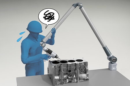
However, measurements using hand tools present problems such as varying measured values among operators, and requiring multiple workers and taking long time. Coordinates cannot even be obtained in GD&T measurement. When an arm CMMs is used, it needs to be moved during measurement due to the small measurement range and skill is required for its operation.
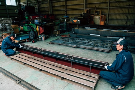
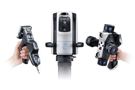
To solve these problems, the latest CMMs are used in an increasing number of cases. KEYENCE’s Wide Area Coordinate Measuring Machine WM Series enables high-accuracy dimensional measurement of jigs over a large area with the wireless probe. Even recessed areas can be reached with no movement restrictions within the measurement range, which allows for easy single-person measurement with the simple operation of touching jigs with the probe. Unlike measurements using hand tools such as tape measures, calipers, and dial gauges, results do not vary, enabling quantitative measurement. Additionally, dimensions can be measured directly in three dimensions on the basis of reference virtual lines, which ensures parallelism and perpendicularity with high reliability.
Flatness and parallelism measurement of positioning jigs
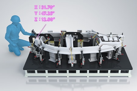
The measurement distance of positioning jigs used for large-scale products is on the order of several meters, so their positions are measured using tape measures or calipers. The installation angle and flatness are measured using other measuring instruments such as dial gauges and angle gauges. However, measured values obtained with these hand tools vary according to the angle, strength, and position at which the tools are applied to the target, which causes variations in measured values among operators.
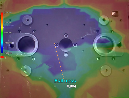
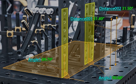
With the WM Series, it is possible for a single person to perform quantitative measurement with no variations by simply touching measurement points with the probe. The angle of installed jigs can also be measured by simply touching with the probe. Even 3D position coordinates can be measured. GD&T such as flatness (form tolerance) and parallelism (orientation tolerance) can also be measured with high accuracy. This enables operators to measure important dimensions, which were measured using conventional measuring instruments, while intuitively checking measurement points on the monitor.
The WM Series is portable and thus can meet the need to measure 3D installation accuracy on-site, which is impossible with ordinary CMMs.
Comparison measurement between XYZ coordinates of a welding jig and CAD data
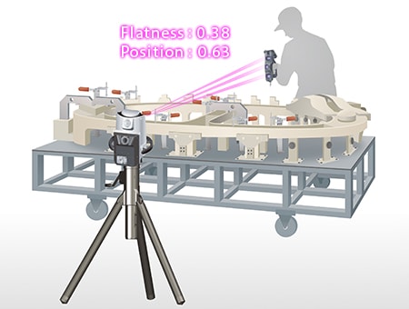
Parts positioning using welding jigs directly affects the final accuracy of welded products. It is important to check if welded products have been processed in conformance to CAD drawings. Welded product dimensions cannot be compared with CAD drawings when measured using hand tools, such as tape measures, calipers, and dial gauges, because it is difficult to measure 3D position coordinates using these tools. Additionally, measured values obtained with these tools vary from operator to operator. When an arm CMM is used, it needs to be moved during measurement due to its small measurement range. Furthermore, its operator must be highly skilled.
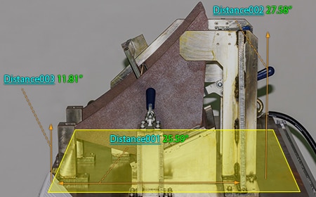
With the WM Series, it is possible for a single person to perform 3D position coordinate measurement with no variations by simply touching measurement points with the probe. GD&T, such as position and flatness, can also be measured directly along with XYZ coordinates. This enables quantitative measurement of important dimensions that need to be controlled, which were measured using conventional measuring instruments, while intuitively checking measurement points on the monitor.
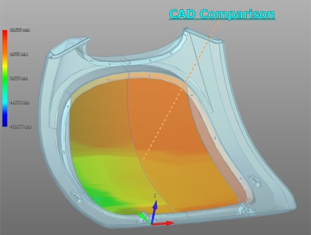
Comparison measurements are possible between a part being measured and a shape imported from a 3D CAD file. Differences from CAD drawings can be checked at measurement sites. The points of difference between the part and 3D CAD data can be displayed as a color map, which enables visual checking of differences.
Optimization of Dimensional Measurement of Positioning and Welding Jigs
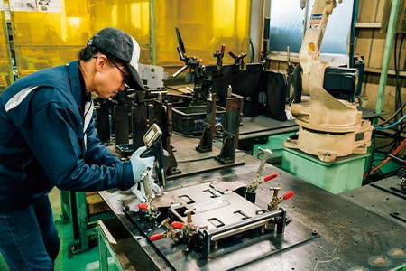
The WM Series enables single-person measurement of positioning and welding jigs with the simple operation of touching targets with the wireless probe. In addition to the features introduced above, the WM Series has the following advantages.
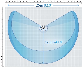
- High-accuracy measurement over a large area
- A wide measurement range up to 25 m (82.0'′) can be measured with high accuracy. The WM Series is equipped with the navigation measurement mode, which enables measurement at the same point according to a memorized measurement procedure, allowing anyone to obtain the same measurement data.
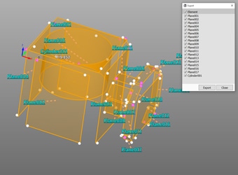
- Measurement results can be output as 3D models
- The measured elements can be exported as a STEP/IGES file. 3D CAD data can be created on the basis of the measurement results of an actual product even if no drawing is available.
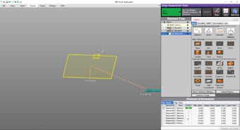
- Easy-to-understand interface
- CMM interfaces are often a mess of complex and unfamiliar commands. The WM Series provides intuitive operation using images and icons, so anyone can easily understand how to operate the system.
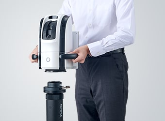
- The portable body can be placed on-site
- The main unit can be carried around on the cart. The WM Series can be brought into worksites and immediately measure the status of work.
The WM Series strongly supports analysis, such as comparison with 3D CAD data, as well as dimensional measurement of positioning jigs. It dramatically improves the efficiency of manufacturing jigs and of work performed during their installation and maintenance.


