
Optimization of Trajectory Measurement for Transfer Machines and Industrial Robots
The digital transformation of the manufacturing and logistics industries has lead to the automation of work in factories and logistics centers. A typical example of this automation is the introduction of transfer machines and industrial robots, devices that are now seen as indispensable.
However, there are cases in which bottlenecks arise from the inaccurate work performed by these devices or their inability to keep up with the line speed.
The major cause of these issues is insufficient operation accuracy, and measuring the trajectories of the moving parts makes it possible to identify the problems.
This section explains the basic knowledge of trajectory measurement for transfer machines and industrial robots, the necessity of this measurement, and the measurement points. It also introduces various examples for optimizing these measurements while focusing on the differences in measurement efficiency arising from differences in measuring instruments.
- What Is the Trajectory of a Transfer Machine or Industrial Robot?
- Trajectory Characteristics
- Necessity of Trajectory Measurement for Transfer Machines and Industrial Robots
- Trajectory Measurement for Transfer Machines and Industrial Robots
- Problems of Trajectory Measurement for Transfer Machines and Industrial Robots and Their Solutions
- Optimization of Trajectory Measurement for Transfer Machines and Industrial Robots
What Is the Trajectory of a Transfer Machine or Industrial Robot?

The trajectory of a transfer machine or industrial robot refers to the path taken by the robotic hand and joints during the operation of the industrial robot or the moving parts of the transfer machine.
In warehouses, factories, and similar locations, transfer machines and industrial robots excel at accurate, repetitive work. Operation at the predetermined speed and positioning accuracy are the most important features when it comes to this accurate, repetitive work. To realize these two features, items such as the moving parts of the transfer machine and the robotic hand and joints of the industrial robot must move through the correct trajectory.
Trajectory Characteristics
The trajectory characteristics vary depending on the device. This section introduces the characteristics of the trajectories drawn by vertical transfer machines and by vertical multi-joint robots.
Transfer machine trajectory
There are many types of transfer devices including lift devices, conveyors, and automated guided vehicles. Among these devices, one type of lift device is the vertical transfer machine, which has a long movement distance and requires high straightness to maintain normal operation of the ascending/descending cage.
A vertical transfer machine is a device installed in buildings such as logistics centers and factories to transfer loads vertically. It differs from a load elevator in that it does not correspond to the elevatory systems prescribed in the Building Standards Act of Japan and, therefore, does not require an application for building confirmation, the permission of the labor standards bureau, periodic inspections and reports after installation, or similar items. Because it is specialized for transferring loads, it can do so at higher speeds, building an efficient transfer system in combination with transfer machines for storing and shipping. Consequently, many of these machines are installed in logistics centers, factories, and similar locations.
A vertical transfer machine moves up and down in a straight line and at a constant speed. Also, types whose driving mechanisms are equipped with servo motors can accelerate and decelerate smoothly, reducing the stopping time as well as the load on the transferred object and on the mechanical devices. It is even possible to stop these machines before the cage reaches one of the endpoints.
From these operations, vertical transfer machines not only perform linear operation over long distances but also draw diverse trajectories such as stopping before reaching one of the endpoints.
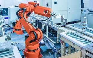
Industrial robot trajectory
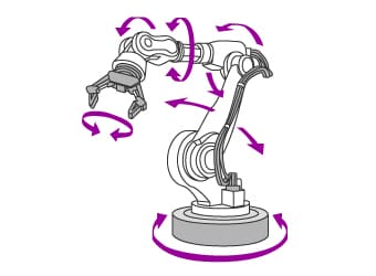
There are many types of industrial robots including vertical multi-joint robots, horizontal multi-joint robots (SCARA robots), and cartesian robots. Vertical multi-joint robots are shaped like the human arm and have a high degree of freedom of movement, allowing the robotic hand and joints to move through complicated trajectories.
Most vertical multi-joint robots are 6-axis devices required for working in three-dimensional spaces. Each joint (also known as an axis) has a built-in servo motor, allowing for complicated and smooth motion, which provides an extremely high level of versatility. Hence, these robots are used in a wide variety of processes including picking, welding, coating, and assembly. However, their structure is more complex and their mechanical rigidity is lower than cartesian robots and similar devices, so it is easy for overshooting and vibrations to occur during high-speed operations, which makes precise control a necessity.
As described here, vertical multi-joint robots (whose delicate mechanisms allow for freedom of movement) move through the most complicated trajectories of a wide variety of industrial machines.
Necessity of Trajectory Measurement for Transfer Machines and Industrial Robots
The operation trajectories of transfer machines and industrial robots change depending on factors such as the load caused by the product being transferred, the friction between the compositional parts, and the deterioration of the electromagnetic brake of the motor, and these changes have various negative effects on the work performed by these devices.
For example, consider a vertical transfer machine that loads the product transferred from a conveyor into the ascending/descending cage at the accurate position, moves to the upper/lower level, and then discharges the product onto the next conveyor. As the product being transferred gets heavier, the load on the motor increases, preventing the vertical transfer machine from operating along the ideal trajectory. Consequently, the electromagnetic brake deteriorates, resulting in the machine no longer being able to stop at the correct position. Also, guide rail distortions lead to trajectory instability.
With industrial robots that automatically grip and transfer products, if the performance of the motors installed in the joints or the rigidity of the arm is insufficient, the trajectory of the robotic hand, arm, or joints will be unstable, leading to longer positioning and takt times and making accurate picking and palletizing impossible.
The operation accuracy of transfer machines and industrial robots is affected by various parts including the performance of the motors and the strength of the frame, arm, and joints that make up these devices. Hence, it is very difficult to detect the causes of problems with the operation accuracy. However, by measuring the trajectory accuracy, it is possible to quickly identify the causes of problems such as these. Periodic measurements can make changes in the operation status of equipment clear, allowing for preventive and predictive maintenance of transfer machines and industrial robots.
Trajectory Measurement for Transfer Machines and Industrial Robots
In these measurements, the target is the trajectory drawn in the air by the moving parts. Therefore, the things to keep in mind are different than when measuring the dimensions of general products.
Measurement points
The trajectory measurement points differ between transfer machines and industrial robots. This section introduces the measurement points with the examples of a vertical transfer machine and a vertical multi-joint robot.
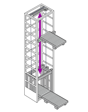
Vertical transfer machine
For a vertical transfer machine, the trajectory of the ascending/descending cage is measured. A measurement of whether the conveyor or package stand within this cage ascends in a straight line and stops at the correct position allows for a check of the operation accuracy.
Insufficient drive motor performance leads to overrun in the lower part. Deterioration of the electromagnetic brake of the motor leads to overrun in the upper part and prevents the cage from stopping at the correct position. Also, guide rail distortions lead to instability in the trajectory of the ascending/descending cage.
This description shows the importance for vertical transfer machines of measuring the upper and lower stop positions as well as the trajectory drawn by the conveyor or package stand in the ascending/descending cage as it moves vertically.
Vertical multi-joint robot
For an industrial robot, the trajectories of the robotic hand and joints are measured. These measurements make it possible to check items such as the motor performance and the arm rigidity.
Each industrial robot joint is equipped with a motor, so the difficulty of realizing the operation accuracy is proportional to the number of joints. Robots such as 6-axis multi-joint robots have a large number of motors, so even minor defects in the operation of these motors disrupt the trajectories. Also, insufficient arm rigidity leads to vibrations during operation because the load cannot be fully supported, making it difficult to realize the programmed operations. Furthermore, these issues have a major effect on the positioning accuracy that is important when the robotic hand performs work such as gripping and processing.
Hence, it is vital to measure the trajectories and stop positions of the robotic hand and joints of an industrial robot.
Problems of Trajectory Measurement for Transfer Machines and Industrial Robots and Their Solutions
The trajectories of transfer machines and industrial robots must be checked not only during installation and teaching but also during the periodic maintenance carried out after installation. The movement of the moving parts, actuators, or joints is measured for the trajectory of a transfer machine or industrial robot. The trajectories of linear motions are measured with hand tools such as dial gauges. Three-dimensional trajectories are measured with coordinate measuring machines (CMMs) such as laser trackers.
However, many points need to be measured, so measurement with hand tools takes a lot of time. Also, the measurement accuracy varies greatly depending on the skills of the operators making the measurements. There is also the fundamental problem that it is difficult to measure three-dimensional trajectories.
Laser trackers can measure three-dimensional trajectories but can only be used by a limited number of operators due to the skills required for their operation. There are many cases in which trajectory measurement problems such as these cause delays in manufacturing line startup and malfunctions after manufacturing line installation.
To solve these problems, the latest CMMs are used in an increasing number of cases.
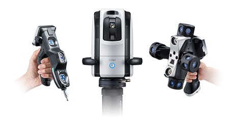
KEYENCE’s Wide Area Coordinate Measuring Machine WM Series can perform high-accuracy measurement by reading the position of the attached wireless probe at the desired measurement point.
Easy, single-person measurement is possible within the measurement range even when measuring a transfer machine trajectory with a long linear distance or the three-dimensional trajectory of the robotic hand of an industrial robot. Also, unlike hand tools, measurement results do not vary, enabling quantitative measurement. The measurement data is saved instantly, allowing for comparison with the design data, which is useful in quality management.

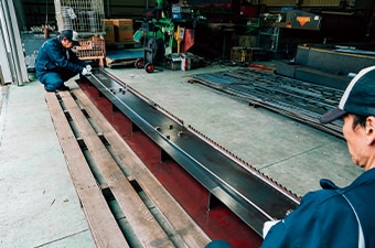
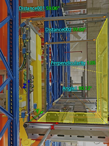
Transfer machine trajectory distortion measurement
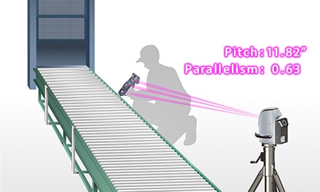
To measure transfer machine trajectory distortion with a dial gauge, laser range finder, or similar tool, it is necessary to stop the transfer machine at the position to measure. The measurement accuracy is proportional to the number of positions to measure, so an enormous number of stops is necessary if high accuracy is required.
Also, the measured value varies depending on the position to measure and the way the measuring instrument is touched to the target, so accurate measurement requires knowledge of and techniques for measurement methods, measuring instrument handling, and similar topics. Hence, measuring transfer machine trajectory distortion with a dial gauge, laser range finder, or similar tool requires an enormous amount of time and skilled operators.
The wireless probe of the WM Series can be attached to the moving part of the transfer machine, allowing for trajectory measurement simply by reading the trajectory of this probe. The wide measurement range allows for easy, high-accuracy single-person measurement of long-distance trajectories, and issues such as guide rail warpage and distortion can be checked from the obtained data. The three-dimensional coordinates of each point can also be measured, allowing for measurement of the straightness and parallelism of the trajectory.
Also, the WM Series immediately saves the measurement results as data, enabling comparison of the trajectory read from a 3D CAD file and the trajectory in the program and outputting of the measurement results as CAD data.
The tracking camera of the WM Series tracks the probe to identify its position and orientation with high accuracy, and the probe search camera tracks the light emitted from the wireless probe at all times. Hence, the probe position can be identified instantaneously wherever the probe is within the wide measurement area.
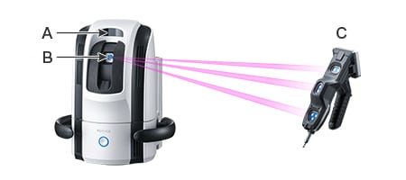
- A
- Tracking camera
- B
- Probe search camera
- C
- Wireless probe
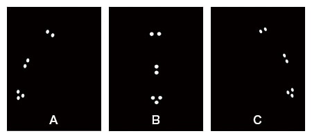
- A
- Tilted to the left
- B
- Center
- C
- Tilted to the right
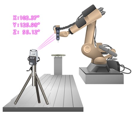
Industrial robot trajectory measurement
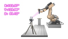
Measuring the stop position and trajectory of the robotic hand of an industrial robot with a laser tracker or similar instrument requires a large amount of knowledge regarding the measuring instrument and the measurement method. Due to the skills required for their operation, these instruments can only be used by a limited number of operators. Also, it is difficult to measure the three-dimensional trajectories of industrial robots with hand tools such as dial gauges.
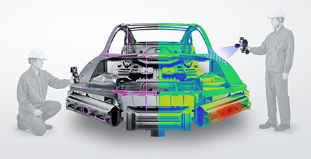
The wireless probe of the WM Series can be attached to the robotic hand, allowing for trajectory measurement simply by reading the trajectory of this probe. Easy, single-person measurement is even possible for the three-dimensional trajectories of a 6-axis vertical multi-joint robot. Trajectories can be measured with user-set virtual lines and reference coordinates, and the auto trigger function can be used to acquire a trajectory as consecutive point-cloud data.
Additionally, the WM Series is portable and thus can meet the need to measure 3D installation accuracy on-site, which is impossible with ordinary CMMs.
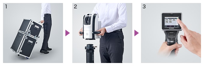
- 1
- Carry: The WM Series comes with a dedicated, mobile case.
- 2
- Set up: Just connect two cables.
- 3
- Press the button
Optimization of Trajectory Measurement for Transfer Machines and Industrial Robots
The WM Series enables single-person measurement of the trajectories of transfer machines and industrial robots with the simple operation of attaching the wireless probe to the measurement point. In addition to the features introduced above, the WM Series has the following advantages.
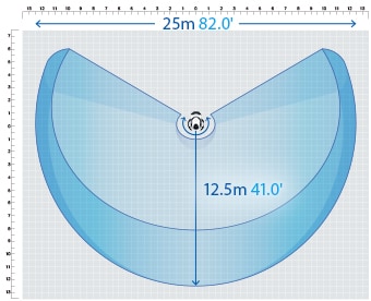
- High-accuracy measurement over a large area
- A wide measurement range up to 25 m (82.0'′) can be measured with high accuracy. The WM Series is equipped with the navigation measurement mode, which enables measurement at the same point according to a memorized measurement procedure, allowing anyone to obtain the same measurement data.
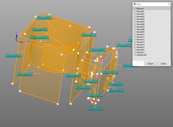
- Measurement results can be output as 3D models
- The measured elements can be exported as a STEP/IGES file. 3D CAD data can be created on the basis of the measurement results of an actual product even if no drawing is available.
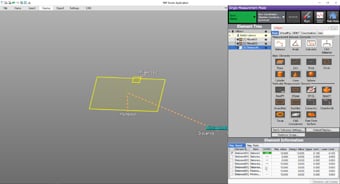
- Easy-to-understand interface
- CMM interfaces are often a mess of complex and unfamiliar commands. The WM Series provides intuitive operation using images and icons, so anyone can easily understand how to operate the system.
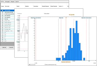
- Statistical analysis function for summarizing data
- Measurement results from guided measurement will be automatically saved to the hard disk drive. Saved data can then be extracted for use with various statistic analyses such as checks of the statistical values, trend graphs, and histograms.
The WM Series strongly supports analysis, such as comparison with 3D CAD data, as well as measurement of the trajectories of transfer machines and industrial robots. It dramatically improves the efficiency of work including the manufacturing of transfer machines and industrial robots as well as their post-installation operation checks, teaching, and maintenance.
