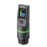
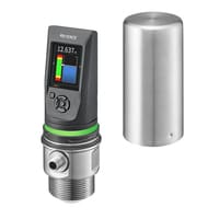
Radar Level Sensor
FR series
Specs Radar Level Sensor FR series
Sensor Unit
|
Model |
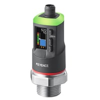
FR-S01 |
FR-SH01 |
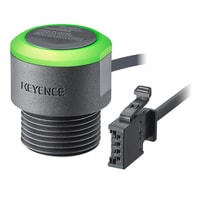
FR-LW20 |
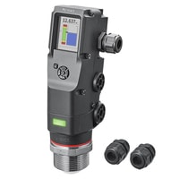
FR-LM20L |
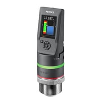
FR-LP20L |
FR-LS20L |
|||
|
Image |
|
|
|
|
|
|
|||
|
Type |
Short range Standard model |
Short range Compact chemical model |
2-wire standard model |
Long range Standard model |
Long range Chemical model |
Long range Sanitary model |
|||
|
Measuring range |
Up to 1.5 m 4.9'*1 |
Up to 20 m 65.6'*7 |
Up to 15 m 49.2'*1 |
||||||
|
Display range |
Up to 2 m 6.6'*1 |
Up to 25 m 82.0'*7 |
Up to 25 m 82.0'*1 |
||||||
|
Measurable dielectric constant of medium |
2 or higher*2 |
2 or more*8 |
2 or higher*2 |
||||||
|
Resolution |
1 mm 0.04" |
||||||||
|
Precision |
Up to 0.1 m 0.3': ±20 mm 0.79"; |
Up to 0.1 m 0.3': ±10 mm 0.39"; |
Up to 0.1 m 0.3': ±10 mm 0.39"; |
||||||
|
Response time |
0.4 s, 1.5 s, 4 s (default value), 10 s |
1 s, 4 s (default value), 10 s, 25 s |
0.4 s, 1.5 s, 4 s (default value), 10 s |
||||||
|
Tank pressure |
-0.1 to +1 Mpa |
-0.1 to +0.1 Mpa |
-0.1 to +1 MPa (-0.1 to +0.1 MPa below -20°C -4°F) |
-0.1 to +1 MPa |
-0.1 to +0.1 Mpa |
-0.1 to +1 Mpa |
|||
|
Material |
Tank interior |
Lens: PTFE |
Lens: PTFE |
Lens: PTFE; |
Lens: PTFE |
Lens: PTFE |
Lens: PTFE |
||
|
Housing |
PBT PAR |
PPS PPSU |
PPS PC PA |
PPS PET PAR |
PPS PPSU |
SUS304 |
|||
|
Connection diameter |
G3/4 (20 A) |
G1-1/2 (40A) |
G1-1/2 (40 A) |
2 S ferrule |
|||||
|
Output |
No. of control outputs |
Maximum 5 |
─ |
1 |
Maximum 5 |
||||
|
Control output/auxiliary output |
NPN/PNP open collector (switching type) |
Transistor output (NPN open collector) |
NPN/PNP open collector (switching type) |
||||||
|
Analog output |
0–20 mA/4–20 mA |
4 to 20 mA (Response time: 3 s after internal value is confirmed [90% response]) |
0–20 mA/4–20 mA maximum load resistance 260 Ω |
||||||
|
External input |
Short-circuit current: 1.5 mA or less |
─ |
|||||||
|
Network compatibility |
IO-Link v1.1/COM2 |
IO-Link v1.1/COM2 |
|||||||
|
Analog output accuracy |
Resolution |
1 mm 0.04"*4 |
1 mm 0.04"*10 |
1 mm 0.04"*4 |
|||||
|
Zero accuracy |
±0.1 mA (zero point = 4 mA)*4 |
±0.1 mA (zero point = 4 mA)*10 |
±0.1 mA (zero point = 4 mA)*4 |
||||||
|
F.S. accuracy |
±0.2 mA (full-scale = 20 mA)*4 |
±0.2 mA (full scale = 20 mA)*10 |
±0.2 mA (full-scale = 20 mA)*4 |
||||||
|
Power supply |
Power voltage |
24 VDC + 25%/–20% Including ripple Class 2 or LPS |
18.3 to 35 VDC. |
24 VDC + 25%/–20% |
|||||
|
Power consumption |
80 mA or less (Excluding Load Current) |
752.5 mW or less (including analog output; excluding load current) |
106 mA or less (Excluding Load Current) |
98 mA or less (Excluding Load Current) |
106 mA or less (Excluding Load Current) |
||||
|
Environmental resistance |
Ambient temperature |
−20°C to +55°C*5*6 -4°F to +131°F |
–10 to +70°C*5*614°F to 158°F |
-30 to +60°C -22 to 140°F (no freezing) |
Display part when combined and separated: –20 to +50°C -4°F to+122°F(no freezing)*5*6 |
Display part when combined and separated: –10 to +50°C 14°F to 122°F (no freezing)*5*6 |
−20°C to +60°C*5*6 -4°F to+140°F (no freezing) |
||
|
Relative humidity |
Up to 85% RH (no condensation) |
||||||||
|
Temperature of coupling used |
–20 to +85°C -4°F to +185°F (no freezing)*5*6 |
–10 to +85°C 14°F to 185°F (no freezing)*5*6 |
-30 to +85°C -22 to 185°F (no freezing) |
–20 to +85°C -4°F to +185°F (no freezing)*5*6 |
–10 to +85°C 14°F to 185°F (no freezing)*5*6 |
–20 to +100°C -4°F to+ 212°F (no freezing)*5*6 |
|||
|
Vibration resistance |
10–500 Hz Power spectral density: 0.816 G2; X, Y and Z directions |
10 to 500 Hz; Power spectral density: 0.816 G2 X, Y and Z directions |
10–500 Hz Power spectral density: 0.816 G2; X, Y and Z directions |
||||||
|
Shock resistance |
100 m/s2 (10 G), 16 ms pulses, 1000 times each for X, Y and Z directions |
100 m/s2 (10 G), 16 ms pulses, 1000 times each in X, Y and Z directions |
100 m/s2 (10 G), 16 ms pulses, 1000 times each for X, Y and Z directions |
||||||
|
Enclosure rating |
IP67 (IEC60529) |
IP67 (IEC60529), Enclosure Type 4X (NEMA250) |
IP67 (IEC60529), IP69K (ISO20653) |
||||||
|
Protection circuit |
Protection against reverse power connection, power supply surges, output overcurrent protection, and output surges |
Reverse power connection protection, power supply surge protection, output short-circuit protection, output surge protection |
Protection against reverse power connection, power supply surges, output overcurrent protection, and output surges |
||||||
|
Weight |
Approx. 170 g 6.00 oz |
Approx. 140 g 4.94 oz |
Approx. 920 g 32.45 oz |
Approx. 600 g 21.16 oz |
Approx. 400 g 14.11 oz |
Approx. 900 g 31.75 oz |
|||
|
*1 Guaranteed value in water with the recommended installation. Static water can be measured up to the edge of the lens. An undetectable area on the short-range side is created due to the environment and measurement medium. The maximum measuring distance is also shortened. |
|||||||||
Sensor Unit
|
Model |
FR-LEX20L |
|||
|
Image |
|
|||
|
Type |
2-wire explosion-proof model |
|||
|
Measuring range |
Up to 15 m 49.2'*1 |
|||
|
Display range |
Up to 25 m 82.0'*1 |
|||
|
Measurable dielectric constant of medium |
2 or more *2 |
|||
|
Resolution |
1 mm 0.04" |
|||
|
Precision |
Up to 0.1 m 0.3': ±10 mm 0.39"; |
|||
|
Response time |
1 s, 4 s (default value), 10 s, 25 s |
|||
|
Tank pressure |
-0.1 to +1 MPa (-0.1 to +0.1 MPa below -20°C -4°F) |
|||
|
Material |
Tank interior |
Lens: PTFE; |
||
|
Housing |
PPS PC PA Internal potting agent: Epoxy resin |
|||
|
Connection diameter |
G1-1/2 (40A) |
|||
|
Output |
No. of control outputs |
─ |
||
|
Control output/auxiliary output |
||||
|
Analog output |
4 to 20 mA (Response time: 3 s after internal value is confirmed [90% response]) |
|||
|
Analog output accuracy |
Resolution |
1 mm 0.04"*4 |
||
|
Zero accuracy |
±0.1 mA (zero point = 4 mA) *4 |
|||
|
F.S. accuracy |
±0.2 mA (full scale = 20 mA) *4 |
|||
|
Power supply |
Power voltage |
18.3 to 35 VDC. |
||
|
Power consumption |
752.5 mW or less (including analogue output; excluding load current) |
|||
|
Environmental resistance |
Ambient temperature |
-30 to +60°C -22 to 140°F (no freezing) |
||
|
Relative humidity |
Up to 85% RH (no condensation) |
|||
|
Temperature of coupling used |
-30 to +85°C -22 to 185°F (no freezing) |
|||
|
Vibration resistance |
10 to 500 Hz; Power spectral density: 0.816 G2 X, Y and Z directions |
|||
|
Shock resistance |
100 m/s2 (10 G), 16 ms pulses, 1000 times each in X, Y and Z directions |
|||
|
IECEx |
Explosion-proof performance |
Ex ia IIC T4 Ga or Ex ia IIB T4 Ga Ex ia IIIC T135°C Da |
||
|
Zone |
Zone 0/20 |
|||
|
Electrical ratings |
Ui: 35 VDC / Ii: 142.4 mA / Pi: 1000 mW / Li: 26.2 nH / Ci: 79 nF |
|||
|
Temperature |
-30°C -22°F ≤ Ta ≤ 60°C 140°F / -30°C -22°F ≤ Tp ≤ 85°C 185°F |
|||
|
ATEX and UKEX |
Explosion-proof performance |
II 1 G Ex ia IIC T4 Ga or II 1 G Ex ia IIB T4 Ga II 1 D Ex ia IIIC T135°C Da |
||
|
Zone |
Zone 0/20 |
|||
|
Electrical ratings |
Ui: 35 VDC / Ii: 142.4 mA / Pi: 1000 mW / Li: 26.2 nH / Ci: 79 nF |
|||
|
Temperature |
-30°C -22°F ≤ Ta ≤ 60°C 140°F / -30°C -22°F ≤ Tp ≤ 85°C 185°F |
|||
|
Type Approval of Electrical Equipment for Use in Explosive Atmospheres |
Explosion-proof performance |
Ex ia IIC T4 Ga or Ex ia IIB T4 Ga Ex ia IIIC T135°C Da |
||
|
Zone |
Zone 0/20 |
|||
|
Electrical ratings |
Ui: 35 VDC / Ii: 142.4 mA / Pi: 1000 mW / Li: 26.2 nH / Ci: 79 nF |
|||
|
Temperature |
-30°C -22°F ≤ Ta ≤ 60°C 140°F / -30°C -22°F ≤ Tp ≤ 85°C 185°F |
|||
|
NRTL/ACO |
Explosion-proof performance |
Class I, Zone 0, AEx ia IIC T4 Ga/Zone 20, AEx ia IIIC T135°C Da/Class I, Division 1, Groups A, B, C, D, T4/Class II, Division 1, Groups E, F, G, T135°C/Class III, Division 1 or Class I, Zone 0, AEx ia IIB T4 Ga/Zone 20, AEx ia IIIC T135°C Da/Class I, Division 1, Groups C, D, T4/Class II, Division 1, Groups E, F, G, T135°C /Class III, Division 1 |
||
|
Zone/Division |
Zone 0/20 Division 1 |
|||
|
Electrical ratings |
Ui: 35 VDC / Ii: 142.4 mA / Pi: 1000 mW / Li: 26.2 nH / Ci: 79 nF |
|||
|
Temperature |
-30°C -22°F ≤ Ta ≤ 60°C 140°F / -30°C -22°F ≤ Tp ≤ 85°C 185°F |
|||
|
Enclosure rating |
IP67 (IEC60529), Enclosure Type 4X (NEMA250) |
|||
|
Protection circuit |
Reverse power connection protection, power supply surge protection |
|||
|
Weight |
Approx. 920 g 32.45 oz |
|||
|
*1 Guaranteed value in water with the recommended installation. In still water, measurement is possible with water up to the edge of the lens. An undetectable area is present at short range due to the environment and measurement medium. The maximum measuring range is also reduced. |
||||
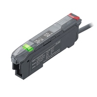
Amplifier unit
|
Model |
FR-SA1 |
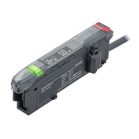
FR-SA2 |
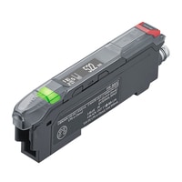
FR-SA1C |
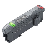
FR-SA0 |
|||
|
Image |
|
|
|
|
|||
|
Type |
Short Separated Amplifier Unit Cable Main Unit |
Short Separated Amplifier Unit Cable Expansion Unit |
Short Separated Amplifier Unit M8 connector Main Unit |
Short Separated Amplifier Unit Zero line Expansion unit |
|||
|
Response time |
0.4 s, 1.5 s, 4 s (default value), 10 s |
||||||
|
Output |
No. of control outputs |
Maximum 5 |
Maximum 2 |
0 |
|||
|
Control output/auxiliary output |
NPN/PNP open collector (switchable) up to 30 VDC or less, max 50 mA for each |
NPN/PNP open collector (switchable) |
─ |
||||
|
Analog output |
0–20 mA/4-20 mA |
─ |
0–20 mA/4–20 mA |
||||
|
External input |
Short circuit current: 1.5 mA or less Input time: 500 ms or more |
||||||
|
External communication |
— |
NU Series compatibility |
IO-Link v1.1/COM2 |
NU Series compatibility |
|||
|
Analog output accuracy |
Resolution |
1 mm 0.04"*1 |
─ |
1 mm 0.04"*1 |
─ |
||
|
Zero accuracy |
±0.1 mA (zero point = 4 mA)*1 |
±0.1 mA (zero point = 4 mA)*1 |
|||||
|
Full-scale accuracy |
±0.2 mA (full-scale = 20 mA)*1 |
±0.2 mA (full-scale = 20 mA)*1 |
|||||
|
Expansion |
Connected to FR-SA1 (with FR-S01 connected): up to 8 units (9 units total including main unit)*2 |
Connected to FR-SA1 (with FR-S01 connected): up to 8 units (9 units total including main unit)*2 |
ー |
With NU series connected:up to 16 units*7 (17 units total including main unit) |
|||
|
Power supply |
Power voltage |
24 VDC +25%/−20%*3*4 including ripple, Class2 or LPS |
|||||
|
Power consumption |
When FR-S01 is connected: up to 1940 mW or less (72 mA or less at 24 V) |
When FR-S01 is connected: up to 1690 mW or less (60 mA or less at 24 V) |
1880 mW or less |
1620 mW max. |
|||
|
Environmental resistance |
Ambient temperature |
–20°C to +55°C -4°F to +131°F (no freezing)*5 |
–20°C to +55°C -4°F to +131°F (no freezing)*8 |
||||
|
Relative humidity |
Up to 85% RH (no condensation) |
||||||
|
Protection circuit |
Protection against reverse power connection, power supply surges, output overcurrent protection, and output surges |
||||||
|
Material |
PC |
||||||
|
Weight |
Approx. 100 g 3.53 oz |
Approx. 90 g 3.17 oz |
Approx. 20 g 0.71 oz |
||||
|
*1 With a load resistance of 250 Ω, this value is guaranteed by KEYENCE inspection facilities. Errors may occur due to your environment. |
|||||||