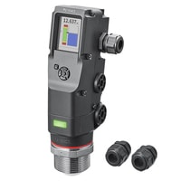
Model | FR-LEX20L |
Type | 2-wire explosion-proof model |
Measuring range | Up to 15 m 49.2'*1 |
Display range | Up to 25 m 82.0'*1 |
Measurable dielectric constant of medium | 2 or more *2 |
Resolution | 1 mm 0.04" |
Precision | Up to 0.1 m 0.3': ±10 mm 0.39";
0.1 to 10 m 0.3' to 32.8' : ±1 mm 0.04";
10 to 20 m 32.8' to 65.6': ±2 mm 0.08"
*3 |
Response time | 1 s, 4 s (default value), 10 s, 25 s |
Tank pressure | -0.1 to +1 MPa (-0.1 to +0.1 MPa below -20°C -4°F) |
Material | Tank interior | Lens: PTFE;
Internal seal: FFKM;
Fastener: SUS304 |
Housing | PPS PC PA Internal potting agent: Epoxy resin
(when using an Isolated barrier) Barrier: PC
(when using a Zener barrier) Barrier: PC
(when using a Zener barrier with a flameproof enclosure) Explosion-proof enclosure: Aluminium die casting, NBR
Cable glands: Nickel-plated brass, chloroprene |
Connection diameter | G1-1/2 (40A) |
Output | No. of control outputs | ─ |
Control output/auxiliary output |
Analog output | 4 to 20 mA (Response time: 3 s after internal value is confirmed [90% response]) |
Analog output accuracy | Resolution | 1 mm 0.04"*4 |
Zero accuracy | ±0.1 mA (zero point = 4 mA) *4 |
F.S. accuracy | ±0.2 mA (full scale = 20 mA) *4 |
Power supply | Power voltage | 18.3 to 35 VDC.
(when using an Isolated barrier) 24 VDC +25%/-10%
(when using a Zener barrier) 20.1 to 28 VDC
(when using a Zener barrier with a flameproof enclosure) 20.1 to 28 VDC |
Power consumption | 752.5 mW or less (including analogue output; excluding load current)
(when using an Isolated barrier) 3 W or less
(when using a Zener barrier) 602 mW or less
(when using a Zener barrier with a flameproof enclosure) 602 mW or less |
Environmental resistance | Ambient temperature | -30 to +60°C -22 to 140°F (no freezing)
(when using an Isolated barrier) Barrier: -30 to +60°C -22 to 140°F (no freezing)
(when using a Zener barrier) Barrier: -30 to +60°C -22 to 140°F (no freezing)
(when using a Zener barrier with a flameproof enclosure) Barrier: -30 to +60°C -22 to 140°F(no freezing) |
Relative humidity | Up to 85% RH (no condensation) |
Temperature of coupling used | -30 to +85°C -22 to 185°F (no freezing) |
Vibration resistance | 10 to 500 Hz; Power spectral density: 0.816 G2 X, Y and Z directions |
Shock resistance | 100 m/s2 (10 G), 16 ms pulses, 1000 times each in X, Y and Z directions |
IECEx | Explosion-proof performance | Ex ia IIC T4 Ga or Ex ia IIB T4 Ga Ex ia IIIC T135°C Da
(when using an Isolated barrier) [Ex ia Ga] IIC or [Ex ia Ga] IIB [Ex ia Da] IIIC
(when using a Zener barrier) [Ex ia Ga] IIB [Ex ia Da] IIIC
(when using a Zener barrier with a flameproof enclosure) Ex db [ia Ga] IIB T4 Gb Ex tb [ia Da] IIIC T135°C Db |
Zone | Zone 0/20
(when using an Isolated barrier) Do not install in a hazardous location (associated apparatus*5)
(when using a Zener barrier) Do not install in a hazardous location (associated apparatus*5)
(when using a Zener barrier with a flameproof enclosure) Zone 1/21 |
Electrical ratings | Ui: 35 VDC / Ii: 142.4 mA / Pi: 1000 mW / Li: 26.2 nH / Ci: 79 nF
(when using an Isolated barrier) Um: 250 VRMS / Uo: 26.78 VDC / Io: 115.307 mA / Po: 772 mW / Lo (IIC): 0.2 mH / Co (IIC): 0.092 μF / Lo (IIB): 0.2 mH / Co (IIB): 0.72 μF
(when using a Zener barrier) Um: 250 VRMS / Uo: 34.33 VDC / Io: 112.007 mA / Po: 961.3 mW / Lo: 1.0 mH / Co: 0.37 μF
(when using a Zener barrier with a flameproof enclosure) Um: 250 VRMS / Uo: 34.33 VDC / Io: 112.007 mA / Po: 961.3 mW / Lo: 1.0 mH / Co: 0.37 μF |
Temperature | -30°C -22°F ≤ Ta ≤ 60°C 140°F / -30°C -22°F ≤ Tp ≤ 85°C 185°F
(when using an Isolated barrier) ─
(when using a Zener barrier) ─
(when using a Zener barrier with a flameproof enclosure) Explosion-proof enclosure: -30°C -22°F ≤ Ta ≤ 60°C 140°F |
ATEX and UKEX | Explosion-proof performance | II 1 G Ex ia IIC T4 Ga or II 1 G Ex ia IIB T4 Ga II 1 D Ex ia IIIC T135°C Da
(when using an Isolated barrier) II (1) G [Ex ia Ga] IIC or II (1) G [Ex ia Ga] IIB II (1) D [Ex ia Da] IIIC
(when using a Zener barrier) II (1) G [Ex ia Ga] IIB II (1) D [Ex ia Da] IIIC
(when using a Zener barrier with a flameproof enclosure) II 2 (1) G Ex db [ia Ga] IIB T4 Gb II 2 (1) D Ex tb [ia Da] IIIC T135°C Db |
Zone | Zone 0/20
(when using an Isolated barrier) Do not install in a hazardous location (associated apparatus*5)
(when using a Zener barrier) Do not install in a hazardous location (associated apparatus*5)
(when using a Zener barrier with a flameproof enclosure) Zone 1/21 |
Electrical ratings | Ui: 35 VDC / Ii: 142.4 mA / Pi: 1000 mW / Li: 26.2 nH / Ci: 79 nF
(when using an Isolated barrier) Um: 250 VRMS / Uo: 26.78 VDC / Io: 115.307 mA / Po: 772 mW / Lo (IIC): 0.2 mH / Co (IIC): 0.092 μF / Lo (IIB): 0.2 mH / Co (IIB): 0.72 μF
(when using a Zener barrier) Um: 250 VRMS / Uo: 34.33 VDC / Io: 112.007 mA / Po: 961.3 mW / Lo: 1.0 mH / Co: 0.37 μF
(when using a Zener barrier with a flameproof enclosure) Um: 250 VRMS / Uo: 34.33 VDC / Io: 112.007 mA / Po: 961.3 mW / Lo: 1.0 mH / Co: 0.37 μF |
Temperature | -30°C -22°F ≤ Ta ≤ 60°C 140°F / -30°C -22°F ≤ Tp ≤ 85°C 185°F
(when using an Isolated barrier) ─
(when using a Zener barrier) ─
(when using a Zener barrier with a flameproof enclosure) Explosion-proof enclosure: -30°C -22°F ≤ Ta ≤ 60°C 140°F |
Type Approval of Electrical Equipment for Use in Explosive Atmospheres | Explosion-proof performance | Ex ia IIC T4 Ga or Ex ia IIB T4 Ga Ex ia IIIC T135°C Da
(when using an Isolated barrier) [Ex ia Ga] IIC or [Ex ia Ga] IIB [Ex ia Da] IIIC
(when using a Zener barrier) [Ex ia Ga] IIB [Ex ia Da] IIIC
(when using a Zener barrier with a flameproof enclosure) Ex db [ia Ga] IIB T4 Gb Ex tb [ia Da] IIIC T135°C Db |
Zone | Zone 0/20
(when using an Isolated barrier) Do not install in a hazardous location (associated apparatus*5)
(when using a Zener barrier) Do not install in a hazardous location (associated apparatus*5)
(when using a Zener barrier with a flameproof enclosure) Zone 1/21 |
Electrical ratings | Ui: 35 VDC / Ii: 142.4 mA / Pi: 1000 mW / Li: 26.2 nH / Ci: 79 nF
(when using an Isolated barrier) Um: 250 VRMS / Uo: 26.78 VDC / Io: 115.307 mA / Po: 772 mW / Lo (IIC): 0.2 mH / Co (IIC): 0.092 μF / Lo (IIB): 0.2 mH / Co (IIB): 0.72 μF
(when using a Zener barrier) Um: 250 VRMS / Uo: 34.33 VDC / Io: 112.007 mA / Po: 961.3 mW / Lo: 1.0 mH / Co: 0.37 μF
(when using a Zener barrier with a flameproof enclosure) Um: 250 VRMS / Uo: 34.33 VDC / Io: 112.007 mA / Po: 961.3 mW / Lo: 1.0 mH / Co: 0.37 μF |
Temperature | -30°C -22°F ≤ Ta ≤ 60°C 140°F / -30°C -22°F ≤ Tp ≤ 85°C 185°F
(when using an Isolated barrier) ─
(when using a Zener barrier) ─
(when using a Zener barrier with a flameproof enclosure) Explosion-proof enclosure: -30°C -22°F ≤ Ta ≤ 60°C 140°F |
NRTL/ACO | Explosion-proof performance | Class I, Zone 0, AEx ia IIC T4 Ga/Zone 20, AEx ia IIIC T135°C Da/Class I, Division 1, Groups A, B, C, D, T4/Class II, Division 1, Groups E, F, G, T135°C/Class III, Division 1 or Class I, Zone 0, AEx ia IIB T4 Ga/Zone 20, AEx ia IIIC T135°C Da/Class I, Division 1, Groups C, D, T4/Class II, Division 1, Groups E, F, G, T135°C /Class III, Division 1
(when using an Isolated barrier) [AEx ia Ga] IIC or [AEx ia Ga] IIB/[AEx ia Da] IIIC Intrinsically safe circuit for Class I, Division 1, Groups A, B, C, D or Class I, Division 1, Groups C, D/Class II, Division 1, Groups E, F, G/Class III, Division 1
(when using a Zener barrier) [AEx ia Ga] IIB/[AEx ia Da] IIIC Intrinsically safe circuit for Class I, Division 1, Groups C, D/Class II, Division 1, Groups E, F, G/Class III, Division 1
(when using a Zener barrier with a flameproof enclosure) Class I, Zone 1, AEx db [ia Ga] IIB T4 Gb/Zone 21, AEx tb [ia Da] IIIC T135°C Db/Class I, Division 1, Groups C, D, T4/Class II, Division 1, Groups E, F, G, T135°C /Class III, Division 1 |
Zone/Division | Zone 0/20 Division 1
(when using an Isolated barrier) Do not install in a hazardous location (associated apparatus*6)
(when using a Zener barrier) Do not install in a hazardous location (associated apparatus*6)
(when using a Zener barrier with a flameproof enclosure) Zone 1/21 Division 1 |
Electrical ratings | Ui: 35 VDC / Ii: 142.4 mA / Pi: 1000 mW / Li: 26.2 nH / Ci: 79 nF
(when using an Isolated barrier) Um: 250 VRMS / Uo: 26.78 VDC / Io: 115.307 mA / Po: 772 mW / Lo (IIC): 0.2 mH / Co (IIC): 0.092 μF / Lo (IIB): 0.2 mH / Co (IIB): 0.72 μF
(when using a Zener barrier) Um: 250 VRMS / Uo: 34.33 VDC / Io: 112.007 mA / Po: 961.3 mW / Lo: 1.0 mH / Co: 0.37 μF
(when using a Zener barrier with a flameproof enclosure) Um: 250 VRMS / Uo: 34.33 VDC / Io: 112.007 mA / Po: 961.3 mW / Lo: 1.0 mH / Co: 0.37 μF |
Temperature | -30°C -22°F ≤ Ta ≤ 60°C 140°F / -30°C -22°F ≤ Tp ≤ 85°C 185°F
(when using an Isolated barrier) ─
(when using a Zener barrier) ─
(when using a Zener barrier with a flameproof enclosure) Explosion-proof enclosure: -30°C -22°F ≤ Ta ≤ 60°C 140°F |
Enclosure rating | IP67 (IEC60529), Enclosure Type 4X (NEMA250)
(when using an Isolated barrier) Barrier: Not specified
(when using a Zener barrier) Barrier: Not specified
(when using a Zener barrier with a flameproof enclosure) Explosion-proof enclosure : IP67 (IEC60529) Enclosure Type 4X (NEMA250) |
Protection circuit | Reverse power connection protection, power supply surge protection |
Weight | Approx. 920 g 32.45 oz
(when using an Isolated barrier) Barrier: Approx. 320 g 11.28 oz
(when using a Zener barrier) Barrier: Approx. 100 g 3.52 oz
(when using a Zener barrier with a flameproof enclosure) Flameproof enclosure + barrier (without cable glands): Approx. 1300 g 45.85 oz |


