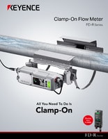
Clamp-on Flow Meter
FD-R series
Sensor Main Unit 40A/50A Type FD-R50

*Please note that accessories depicted in the image are for illustrative purposes only and may not be included with the product.
Specifications
Model | FD-R50 | |||
Supported pipe diameter | 1 1/2" (40 A), ø44 to ø55 1.73" to 2.17" | |||
Supported pipe materials | Metal / resin*1 | |||
Supported fluids | Various liquids (i.e. water, oils, chemicals)*1 | |||
Supported fluid temperature | - 20 to + 120°C - 4.0 to + 248 °F (no freezing on the pipe surface)*2 | |||
Maximum rated flow | Rated flow velocity range: 5.0 m/s | |||
Zero cut flow rate | Zero cut: 0.3 m/s (default)*3 | |||
Display method | Dual row, 5-digit display with white, 14-segment LED; Large status indicator; Output indicators; Stability indicator; Unit indicator | |||
Display update cycle | Approx. 3 Hz | |||
Display resolution | 0.1 / 1 (L / min) | |||
Response time | 0.5 s / 1.0 s / 2.5 s / 5.0 s / 10.0 s / 30.0 s / 60.0 s / 120.0 s / 200.0 s (variable) | |||
Measurement accuracy | Between 20 and 100% of F.S. : ±2.0% of RD*4*5 | |||
Protection circuit | Power supply reverse connection protection, Power supply surge protection, Short-circuit protection for each output, Surge protection for each output | |||
Zero point error | ±0.5% of F.S.*4*6 | |||
Hysteresis | Variable | |||
Flow units | L / min, m3 / h, gal / min | |||
Integrated flow unit display | 1 / 10 / 100 / 1000 / 10000 (L) | |||
Pipe temperature measurement accuracy | ±3°C ±5.4°F (liquid temperature of - 20 to + 50°C, - 4 to + 122°F) | |||
Wiring specifications | Power supply | DC power supply: M12 4-pin connector / AC power supply: M4 screw terminal block (selectable) | ||
I/O | When using a DC power supply: M12 4-pin connector / when using an AC power supply: M3 screw terminal block | |||
Input/Output (Selectable) | Output (ch.1/ch.2) | Control output / Integrated pulse output / Error output / Temperature alarm, NPN / PNP setting switchable,open collector output 30 VDC or less, max. 100 mA / ch., residual voltage: 2.5 V or less*7 | ||
Analog output (ch.1/ch.2) | Flow rate analog output / Temperature analog output and 4 - 20 mA / 0 - 20 mA (selectable), load resistance: 500 Ω or less*7 | |||
External input (ch.2) | Integrated flow reset input / Flow rate zero input / Origin adjustment input (selectable), short-circuit current: 1.5 mA or less, input time: 20 ms or more*7 | |||
Rating | Power voltage | 20 to 30 VDC including 10% ripple (P-P), Class 2 / 100 to 240 VAC - 15% or + 10% (50 / 60 Hz) | ||
Current consumption | When using a DC power supply: 200 mA or less (load current excluded), 400 mA or less (load current included) When using an AC power supply: 15 VA or less | |||
Environmental resistance | Enclosure rating | IP65 / 67 (IEC60259), IP69K (ISO20653), Enclosure Type 4X (NEMA250) | ||
Ambient temperature | - 20 to + 60°C - 4.0 to 140 °F (no freezing)*2 | |||
Relative humidity | 5 to 90%RH (no condensation) | |||
Vibration resistance | 10 to 55 Hz, compound amplitude 1.5 mm 0.06", XYZ axes 2 hours for each axis | |||
Shock resistance | 100 m/s2 , 16 ms pulse, XYZ axes, 1000 times for each axis | |||
Dimensions | Main unit size: 218.5 mm × 66.9 mm × 70.7 mm 8.60" × 2.63" × 2.78" | |||
Material | Main unit | Body: aluminum die-casting + coating / PPS, display: reinforced glass, connectors: SUS304-equivalent | ||
Unit rear | Rubber | |||
Upper/lower bracket | SUS304 | |||
Weight | Main unit: Approx. 1.0 kg | |||
*1 Liquid must allow for the passage of an ultrasonic pulse, as well as not contain large air pockets or excessive bubbles. Detection may be unstable due to the type and status of the pipes. | ||||


