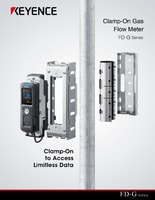
Clamp-On Gas Flow Meter
FD-G series
Clamp-On Gas Flow Meter DN 65A/80A FD-G80L

*Please note that accessories depicted in the image are for illustrative purposes only and may not be included with the product.
Specifications
Model | FD-G80L | |||
Pipe size | DN (Diameter Nominal) | 65 A, 80 A | ||
NPS (Nominal Pipe Size) | 2 1/2", 3" | |||
Outer diameter of pipe | ø72 to 78 mm 2.83" to 3.07", ø86 to 92 mm 3.39" to 3.62" | |||
Pipe thickness | 2.0 to 4.0 mm 0.08" to 0.16" | |||
Supported pipe materials | Iron, steel, stainless steel | |||
Supported fluids | Air, Nitrogen, other gases*1 | |||
Fluid temperature | 0 to 60ºC 32 to 140 °F | |||
Recommended pressure | 0.4 MPa or greater (58 PSI or greater) | |||
Rated velocity of flow range | Up to 15 m/s | |||
Actual flow rate range (typical) | m3/h | Pipe size 65 A: 200.0 | ||
L/min | Pipe size 65 A: 3300 | |||
CFM | Pipe size 65 A: 120.00 | |||
Standard flow rate range (typical) [CFM] | 20°C 68°F 60 psi 0.41 MPa | Pipe size 65 A: 568.43 | ||
20°C 68°F 80 psi 0.55 MPa | Pipe size 65 A: 720.64 | |||
20°C 68°F 100 psi 0.69 MPa | Pipe size 65 A: 872.84 | |||
20°C 68°F 120 psi 0.83 MPa | Pipe size 65 A: 1025.05 | |||
Display | QVGA 2.2" LCD color monitor | |||
Display update cycle | Approx. 3 Hz | |||
Display resolution | Instantaneous flow rate | 0.1 m3/h, 1 L/min, 0.01 CFM | ||
Consumption/leakage amount | 0.01 m3, 1 L, 1 CF | |||
Response time | 1.0 s/2.5 s/5.0 s/10.0 s/30.0 s/60.0 s/120.0 s/200.0 s (variable) | |||
Measurement accuracy | Between 10 and 100% of F.S. | ±2.0% of RD*2*3*4*5 | ||
Between 1 and 10% of F.S. | ±1.0% of F.S.*2*3*4*5 | |||
Zero point error | ±0.15% of F.S.*2*6 | |||
Static leakage repeatability | ±1.0% of RD*4*7 | |||
Hysteresis | Variable | |||
Flow units | CFM(S), CFM, m3/h (N), m3/h (S), m3/h, L/min (N), L/min (S), L/min | |||
I/O wiring connection port | M12 4-pin connector (male) | |||
Detection mode (switchable) | ch.1 | Instantaneous flow mode/area mode/pulse (+) mode/integrated flow mode/warning mode (consump)*8 | ||
ch.2 | Instantaneous flow mode/area mode/pulse (−) mode/warning mode (leak)/error output mode/analog output/integrated flow reset/flow rate zero input/origin adjustment input*8 | |||
Standard I/O (switchable) | Control output (ch.1/ch.2) | NPN/PNP setting switchable, open collector output 30 VDC or less, max. 100 mA/ch, residual voltage: 2.5 V or less | ||
Analog output (ch.2) | 4 to 20 mA/0 to 20 mA, load resistance: 500 Ω or less | |||
External input (ch.2) | Short-circuit current: 1.5 mA or less, input time: 20 ms or more | |||
Protection circuit | Power supply reverse connection protection, power supply surge protection, short-circuit protection for each output, surge protection for each output | |||
Analog input (for volume conversion) | M8 4-pin connector (female), analog current input (4 to 20 mA), input resistance: 100Ω or less | |||
Power supplied to pressure sensor | Supply voltage: Equivalent to voltage applied to the FD-G, Supply current:70 mA or less (analog output of the pressure sensor included) | |||
Communication interface | USB | USB 2.0 | ||
Ethernet | Standard | IEEE 802.3u (100BASE-TX) | ||
Transmission rate | 100 Mbps | |||
Cable | Category 5 or higher STP (shielded twisted pair) or UTP (unshielded twisted pair) cable | |||
Connector | M12 connector (female, D-code) | |||
Network function | Modbus TCP, EtherNet/IP™, IO-Link*9 | |||
Recording capacity | Consumption amount/ leakage amount | Approx. 5 years | ||
Events | 100 | |||
Power supply | Power voltage | 20 to 30 VDC including 10% ripple (P-P), Class 2 | ||
Power consumption | 350 mA or less at 20 V, 290 mA or less at 24 V, 230 mA or less at 30 V (load current excluded) (analog output of the pressure sensor excluded), | |||
Environmental resistance | Enclosure rating | IP65/67 (IEC 60529)*10 | ||
Ambient temperature | Detection head: −10 to +60°C 14 to 140°F (no freezing), display unit: −10 to +55°C 14 to 131°F (no freezing) | |||
Relative humidity | 5 to 85%RH (no condensation) | |||
Vibration resistance | 10 to 500 Hz, power spectral density: 0.816 G2/Hz, XYZ axes | |||
Shock resistance | 100 m/s2, 16 ms pulse, XYZ axes, 1000 times for each axis | |||
Material | Display unit | Body: PBT + coating, display: PMMA, Power supply port: SUS304-equivalent, Ethernet port: zinc nickel plating | ||
Detection head | Body: PPS/SUS304, rear surface: rubber | |||
Mounting/damping bracket | SUS304 | |||
Weight | Approx. 3.6 kg | |||
*1 The gas must be uniform and capable of transmitting ultrasonic waves. Measurement may be unstable due to the pressure inside of the pipe and the type of gas. | ||||


