Digital Microscopes
Observation and Measurement of Electric Wires Using Digital Microscopes
Electric wire is a generic term for metal wires that transmit electric power and signals.
Electric wires can be categorized into power line wires and communication wires according to the intended use. This section provides an overview of electric wires and introduces examples of how to observe and measure them using a digital microscope.
Differences between Electric Wires and Cables

Electric wire is a generic term for metal wires that conduct electricity. Some wires are categorized as cables based on structural differences.
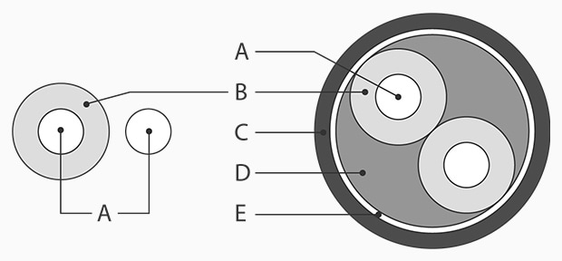
A : Conductor B : Insulator C : Sheath D : Filler E : Binder tape
Electric wire (isolated wire)
An electric wire is a conductor, which transmits electricity, that is covered with an insulator, which does not transmit electricity.
Cable
A cable is a bundle of electric wires covered with a sheath.
Get detailed information on our products by downloading our catalog.
View Catalog

Conductor Materials and Characteristics
Almost all conductors used for electric wires and cables are made from copper or aluminum.
Based only on conductivity, silver and gold are also good materials. However, these materials are rarely used because they are expensive.
Conductor materials and their conductivity and resistivity
| Material | Conductivity (% according to the International Annealed Copper Standard (IACS)) | Resistivity (10-6 Ωm) |
|---|---|---|
|
|
106.4 |
0.0162 |
|
|
100 |
0.0172 |
|
|
71.8 |
0.024 |
|
|
61.7 |
0.0275 |
Characteristics of copper and aluminum
Copper and aluminum conductors used for electric wires and cables have the following characteristics.
Copper
- Copper conducts electricity very easily with its very high conductivity.
- Copper basically does not oxidize in dry air at room temperature.
- Copper is generally used as the conductor in commonly used cables.
Aluminum
- The density of aluminum is lower than copper, with a weight of one-third that of copper. This light material is suitable for long-distance applications such as power lines.
- When aluminum oxidizes, the surface is covered with an alumina layer, which is resistant to corrosion.
- Aluminum is cheap and available at around one-third to half the price of copper.

Differences in Regulations for Electric Wire Cross-sectional Areas between Japan and the United States
In Japan, the cross-sectional areas of electric wires (stranded wires) are regulated with the Japanese Industrial Standards (JIS). The unit is SQ, which originated from an English measure for cross-sectional areas, square millimeter. The UL standards in the United States use American wire gauge (AWG). The table below shows conversions between AWG (UL) and SQ (JIS).
Conversion table between AWG (UL) and SQ (JIS)
| Wire gauge (UL standards) | Outer diameter (mm) | Cross sectional area (mm2) | Corresponding SQ size (JIS) |
|---|---|---|---|
|
|
11.68 mm (0.460″) |
107.2 mm2 |
100 SQ |
|
|
10.40 mm (0.409″) |
85.03 mm2 |
80 SQ |
|
|
9.266 mm (0.365″) |
67.42 mm2 |
60 SQ |
|
|
8.254 mm (0.325″) |
53.49 mm2 |
60 SQ |
|
|
7.348 mm (0.289″) |
42.41 mm2 |
38 SQ |
|
|
6.543 mm (0.258″) |
33.63 mm2 |
38 SQ |
|
|
5.189 mm (0.204″) |
21.15 mm2 |
22 SQ |
|
|
4.115 mm (0.162″) |
13.30 mm2 |
14 SQ |
|
|
3.264 mm (0.129″) |
8.37 mm2 |
8 SQ |
|
|
2.588 mm (0.102″) |
5.26 mm2 |
5.5 SQ |
|
|
2.052 mm (0.081″) |
3.31 mm2 |
3.5 SQ |
|
|
1.628 mm (0.064″) |
2.08 mm2 |
2 SQ |
|
|
1.290 mm (0.051″) |
1.31 mm2 |
1.25 SQ |
|
|
1.024 mm (0.040″) |
0.823 mm2 |
0.75 SQ |
|
|
0.8128 mm (0.032″) |
0.519 mm2 |
0.5 SQ |
|
|
0.6426 mm (0.025″) |
0.324 mm2 |
0.3 SQ |
|
|
0.5105 mm (0.020″) |
0.205 mm2 |
0.2 SQ |
|
|
0.4039 mm (0.016″) |
0.128 mm2 |
0.12 SQ |
|
|
0.3200 mm (0.013″) |
0.0804 mm2 |
0.08 SQ |
|
|
0.2540 mm (0.010″) |
0.0507 mm2 |
0.05 SQ |
Cross-sectional Areas and Allowable Currents of Electric Wires
The larger the cross-sectional area of an electric wire, the larger the allowable current.
The following table shows the allowable currents of typical copper wires.
Allowable current of a single wire
| Diameter (mm) | Allowable current (A) |
|---|---|
|
|
16 |
|
|
19 |
|
|
27 |
|
|
35 |
|
|
48 |
|
|
62 |
|
|
81 |
|
|
107 |
Allowable current of a stranded wire
| Cross sectional area (mm2) | Allowable current (A) |
|---|---|
|
|
17 |
|
|
19 |
|
|
27 |
|
|
37 |
|
|
49 |
|
|
61 |
|
|
88 |
|
|
139 |
|
|
190 |
|
|
298 |
|
|
469 |
|
|
745 |
|
|
930 |
|
|
1080 |
|
|
1260 |
Electric Wire Observation and Measurement Examples Using Digital Microscopes
These are the latest examples of observation and measurement of electric wires using KEYENCE’s VHX Series 4K Digital Microscope.
Observation of electric wire surfaces
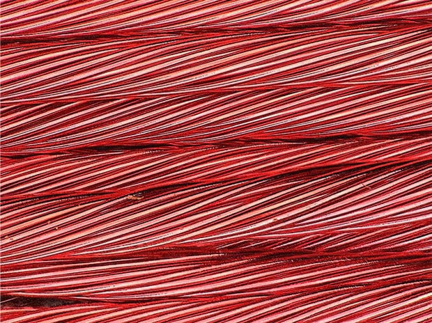
VH-Z20, 100×, ring illumination + diffuse attachment
The diffuse attachment allows for observation with no glare.
Depth composition of a cable cross-section
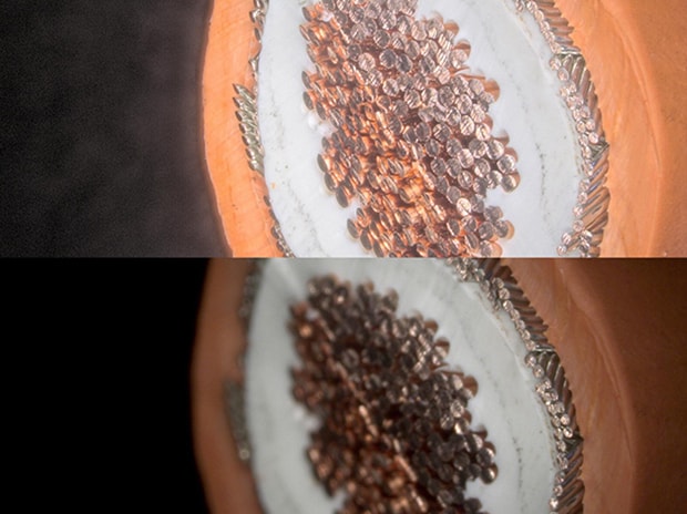
VH-Z20, 30×, ring illumination + HDR
Lower: Normal image, Upper: Depth composition + HDR image
The HDR function allows for detailed observation of cable cross-sections.
Observation of cracks on a metal electric wire surface
Fine surface cracks can be visualized using Optical Shadow Effect Mode.
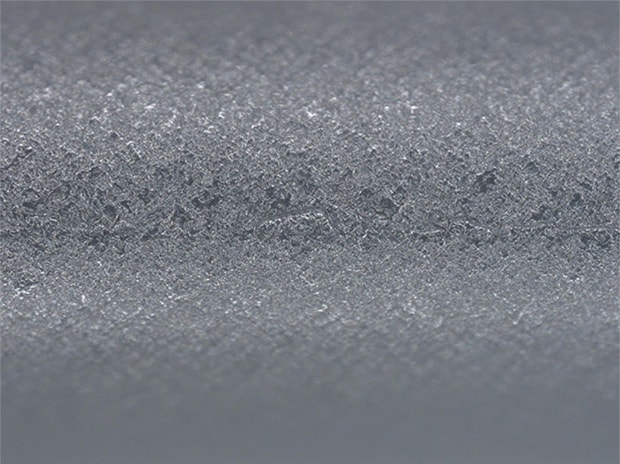
VHX-E100, 100×, ring illumination
Normal image
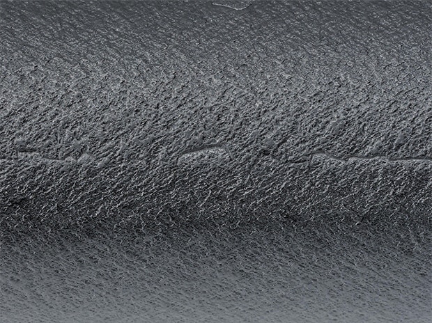
VHX-E100, 100×, ring illumination
Optical Shadow Effect Mode image
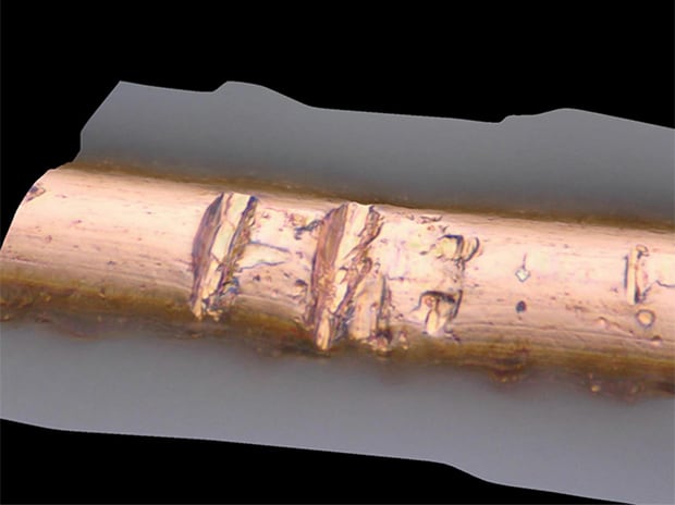
Observation of a peeled copper wire
VHX-E500, 2000×, coaxial illumination
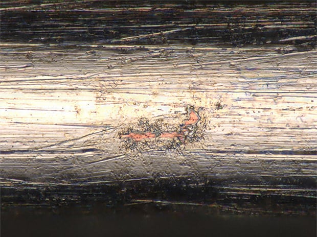
Observation of electric wire defects
VH-Z500, 3000×, coaxial illumination
The 3D depth composition function allows for accurate observation of defect shapes.
Profile measurement of welded parts on an electric wire
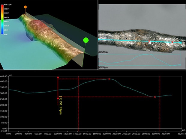
ZS-20, 100×, ring illumination
The weld metal that rises above the surface can be quantified using the 3D measurement function, which allows for accurate OK/NG judgment.
Thickness measurement of copper electric wire sheaths
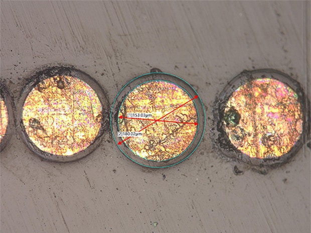
VHX-E500, 500×, coaxial illumination
Quantification of air bubbles in an electric wire sheath
The automatic area measurement function allows for accurate area measurement of each air bubble.
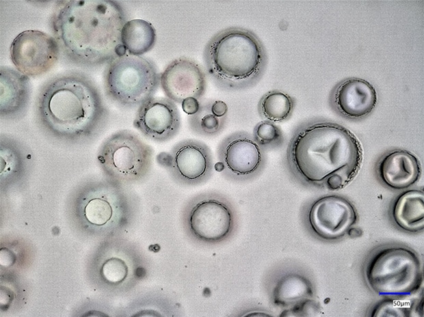
VH-Z500, 500×, coaxial illumination, before measurement
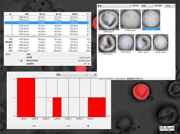
VH-Z500, 500×, coaxial illumination
Automatic area measurement image
Observation of an electric wire sheath surface
Differences of surface conditions caused by differences in materials and manufacturing conditions can be visualized using the 3D depth composition function.
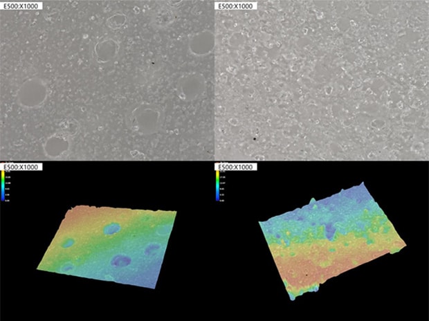
VHX-E500, 1000×, ring illumination
Get detailed information on our products by downloading our catalog.
View Catalog