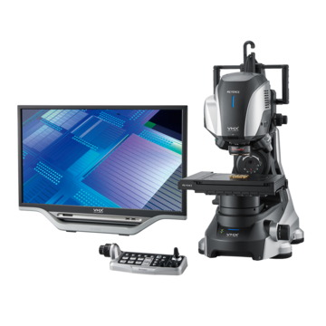
Digital Microscopes
Cutting Tool Types and Observation and Inspection Using a Digital Microscope
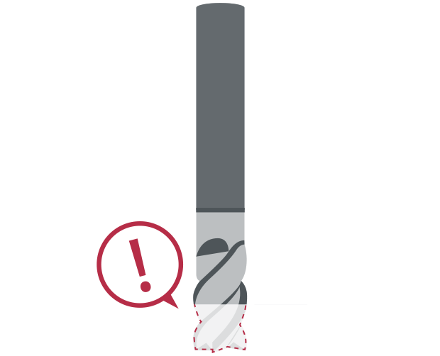
The pursuit of higher strength, greater accuracy, and lighter weight has led to increasing demand for workpieces in difficult-to-cut shapes made from hard-to-cut materials, such as cemented carbide, hard brittle materials, and quenched stainless steel. Hard-to-cut materials put a large strain on cutting tools, so particular attention is required to monitor wear and chips (defects) on the edges of cutting tools. This section introduces types of cutting tools along with examples of observing and analyzing them using our digital microscope.
What is Cutting?
Cutting refers to processing that cuts metal and other materials using tools such as blades.
Another metal processing method, called grinding, scrapes surfaces using a grindstone.
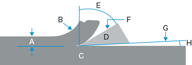
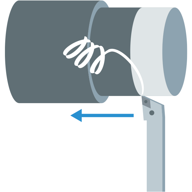
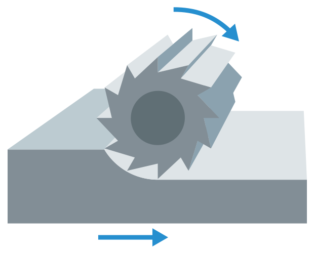
A: Uncut chip B: Chip C: Workpiece D: Tool E: Rake angle F: Rake surface G: Relief surface H: Relief angle
Principle of cutting
A cutting tool continuously chips the target material and generates chips.
In the ideal scenario, chips are generated in a continuous and smooth manner.
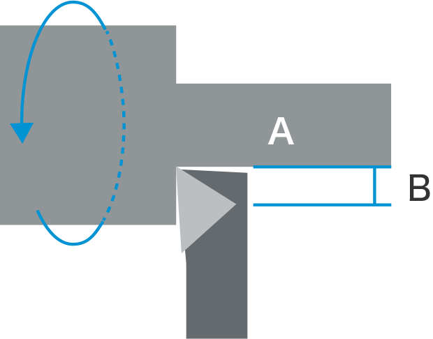
A: Workpiece B: Distance cut per minute
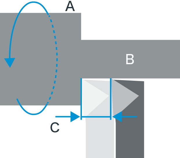
Cutting conditions
The cutting speed, feed speed, and cut amount are all important factors for proper cutting.
Cutting speed = Distance cut per minute (m/min)
Cutting speed (m/min) refers to the distance that a tool cuts per minute.
The faster the cutting speed, the higher the productivity, but the shorter the service life of the tool.
The faster the cutting speed,
the higher the productivity,
but
the shorter the service life of the tool.
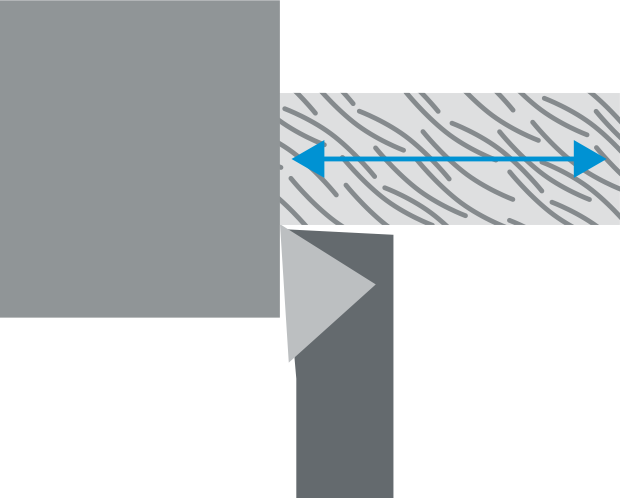
A: One revolution B: Workpiece C: Distance travelled per revolution
Feed speed = Distance to travel per revolution (mm/rev)
The feed speed (mm/rev) refers to the distance that a tool travels per revolution.
As the feed speed increases, productivity increases but so does the roughness of the cut surface.
As the feed speed increases,
productivity increases
but
so does the roughness of the cut surface.
A: Workpiece B: Cut amount
Cut amount = Distance to cut into the workpiece
The cut amount refers to the distance that a tool cuts into the workpiece.
The greater the cut amount, the higher the productivity, but the ideal cut amount is determined by the type and material of the tool.
The greater the cut amount,
the higher the productivity,
but
the ideal cut amount is determined by the type and material of the tool.
Get detailed information on our products by downloading our catalog.
View Catalog

Typical Cutting Methods and Cutting Tools
This section describes typical cutting methods, their characteristics, and the cutting tools that are used.
- Turning
Generally, this method cuts cylindrical or discoidal workpieces into round shapes by turning them.
Machine name: Lathe
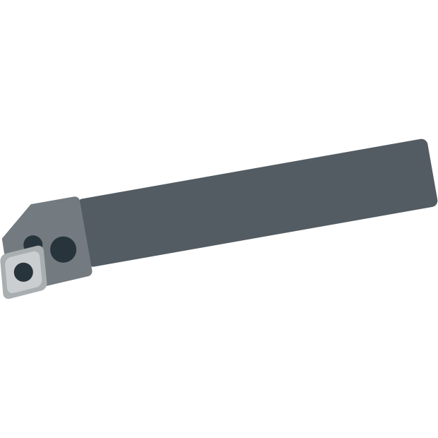
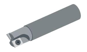
Cutting tool: Tool bit
- Drilling
Tools rotate to make holes in surfaces of workpieces.

Machine name: Drilling machine
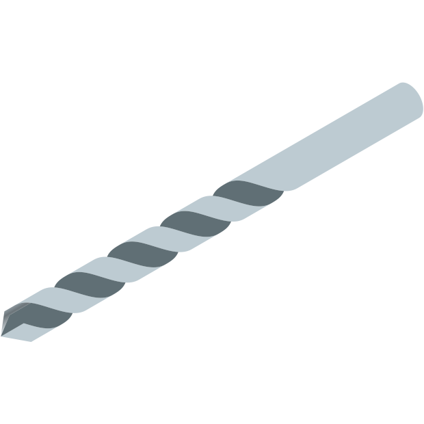
Cutting tool: Drill
- Boring
Tools rotate and machine the inside of drilled holes with high accuracy.
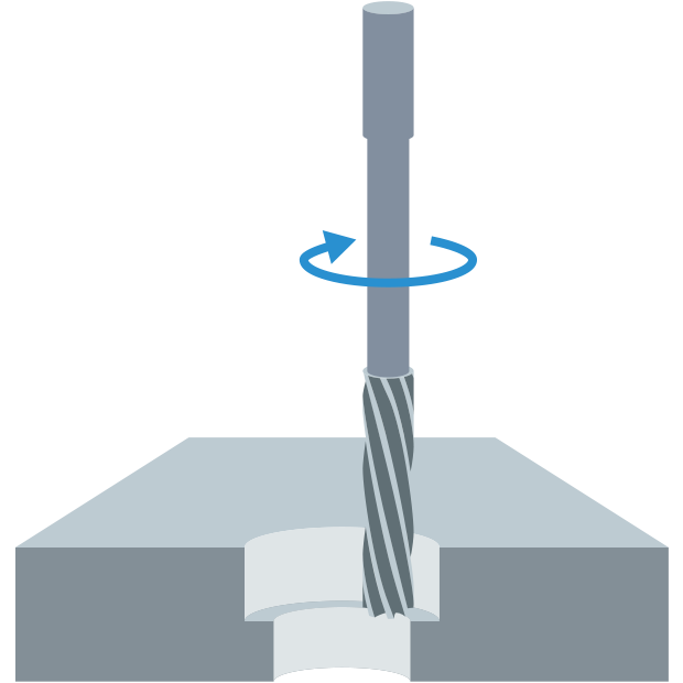
Machine name: Boring machine
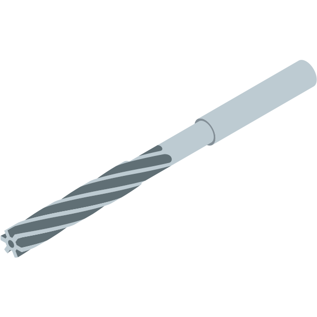
Cutting tool: Reamer
- Broaching
Broaches (tools to finish holes) cut workpieces by moving linearly. Broaching can perform a whole process (through to finishing) with one machine, and it’s easy to estimate the service life of tools. These factors make broaching attractive to the automotive industry where mass production is necessary.
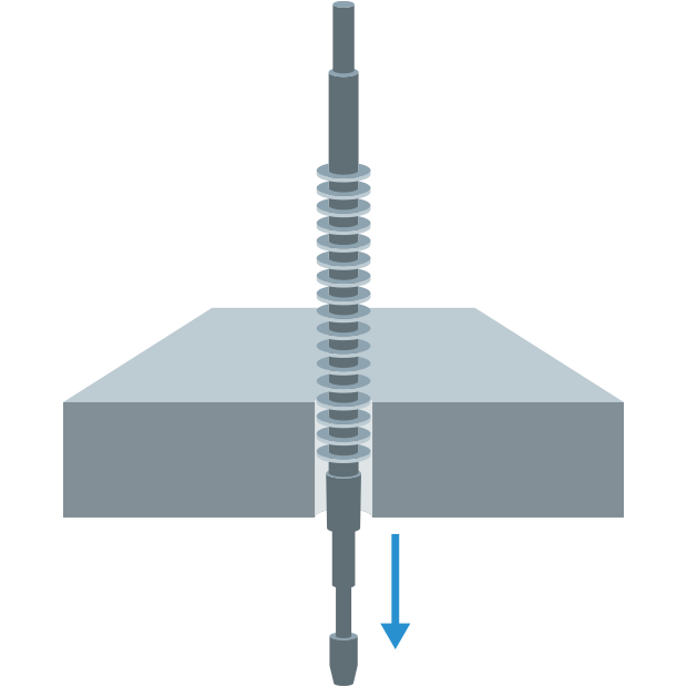
Machine name: Broaching machine
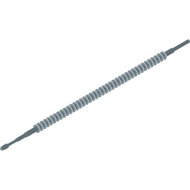
Cutting tool: Broach
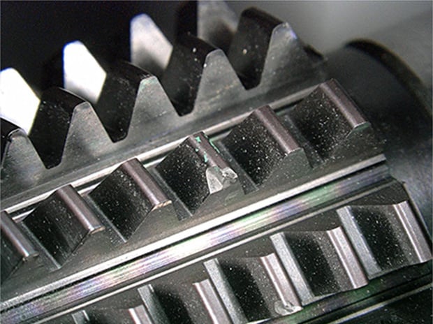
- Gear cutting
Gears are cut with a rotating cutter.
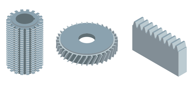
Machine name: Gear cutting machine
Cutting tool: Hob cutter, pinion cutter, rack cutter
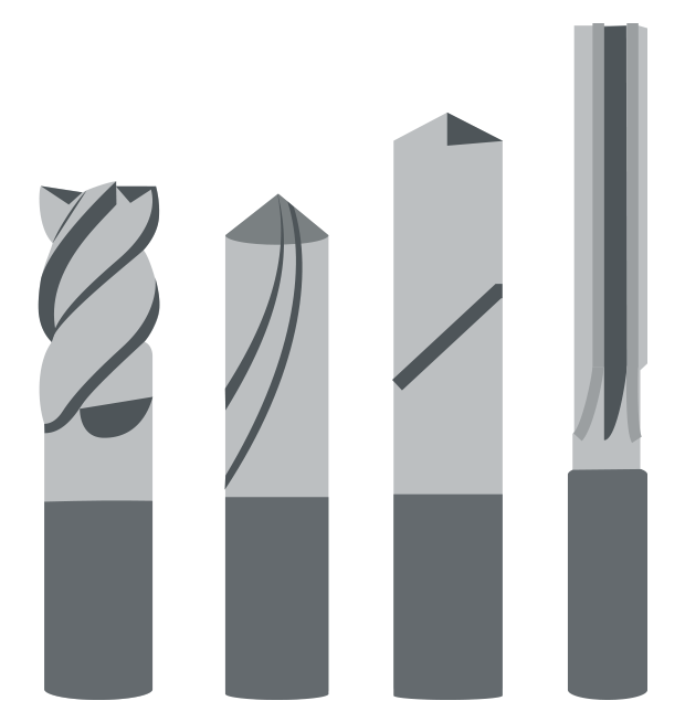
- Milling
Milling removes material by turning a tool called a milling cutter. Milling machines are used to shave surfaces and make grooves. There are generally 2 types: face milling cutters for surface machining, and end mills for grooving.
Machine name: Milling machine
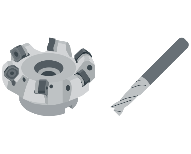
Cutting tool: Face mill, end mill

Typical Tool Materials and Features
This section describes the materials and features of typical cutting tools.
- High-speed steel
Metals, including tungsten, chromium, vanadium, and molybdenum, alloyed with an iron base
Advantage Excellent toughness
Disadvantages Lower heat and wear resistance
Target materials: Carbon and alloy steel - Cemented carbide
Alloys of titanium carbide and tantalum carbide that are added to tungsten carbide powder and then sintered using cobalt.
Advantages Excellent balance of toughness, high hardness, and wear resistance
Target materials: Carbon steel, alloy steel, stainless steel, and other cutting resistant materials - Ceramic
Hard materials, including aluminum oxide, titanium carbide, and silicon nitride, that are sintered.
Advantages Excellent heat and wear resistance
Disadvantages Poor toughness and chip easily
Target materials: Cast iron, heat-resistant alloys, quenched steel, and tool steel - Diamond
Molded material made from diamond monocrystal (the hardest material)
Advantages Excellent heat and wear resistance, and suitable for mirror face cutting
Disadvantages Poor toughness and chips easily
Target materials: Non-ferrous metals including aluminum - Sintered diamond
Polycrystalline body made by adding cobalt to fine diamond powder and sintering.
Advantages Excellent heat and wear resistance, and higher toughness than diamond
Disadvantage Hard to make sharp edges
Target materials: Non-ferrous metals, cemented carbide, ceramics - Cermet
Nickel and other materials are added to titanium carbide and titanium nitride and then sintered.
Advantages A type of cemented carbide. Excellent wear and corrosion resistance compared with normal cemented carbide. It is often used for finishing steel.
Target materials: Carbon and alloy steel
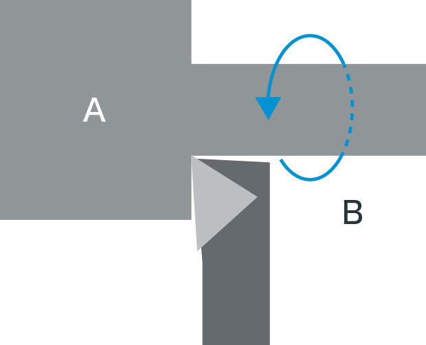
Throwaway Tips
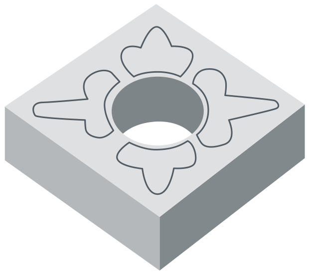
The benefit is that the edge is replaceable and it can be used immediately after replacement.
Throwaway tips are mechanically fixed in holders with screws before use. The material for the edge is generally cemented carbide and the shapes are defined by the ISO (e.g., equilateral triangle, square, rhomboid, and circle).
End mill
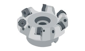
Face mill cutter
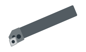
Tool bit
Examples of Observation and Inspection of Cutting Tools Using a Digital Microscope
The latest examples of observation and inspection images of cutting tools using KEYENCE’s VHX Series 4K Digital Microscope are introduced below.
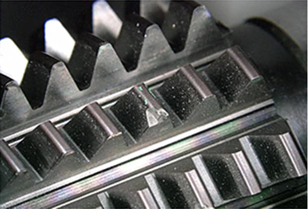
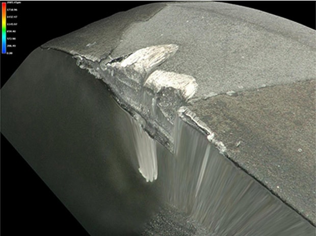
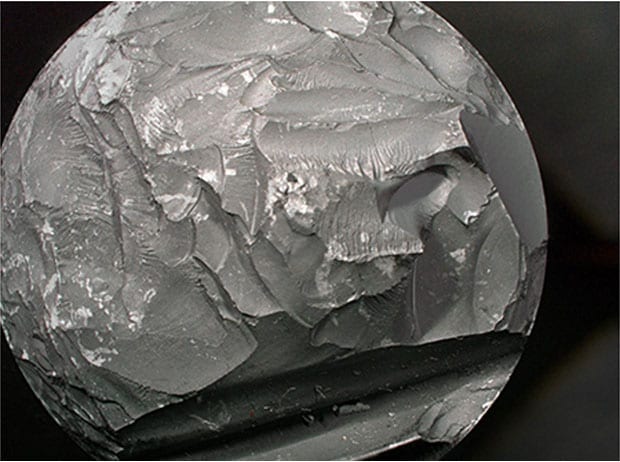
Chipping on a hob cutter edge
20×, ring illumination
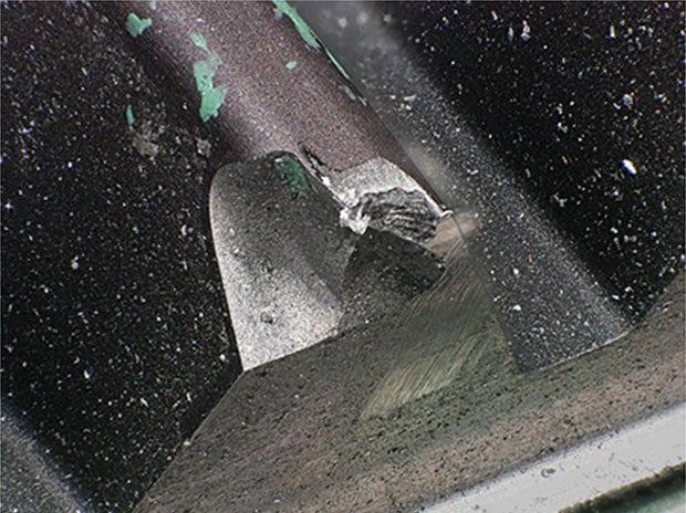
100×, ring illumination
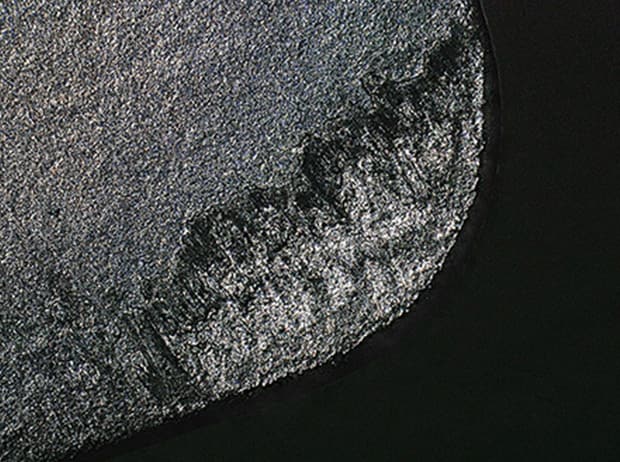
Pinion cutter wear, coating peeling
20×, ring illumination
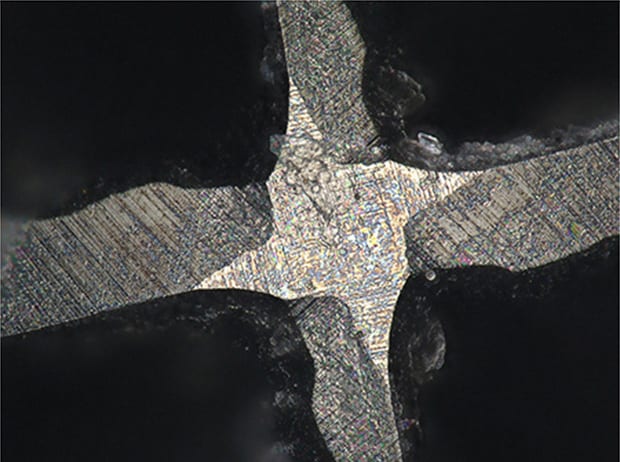
Observation of a reamer edge
20×, ring illumination
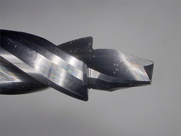
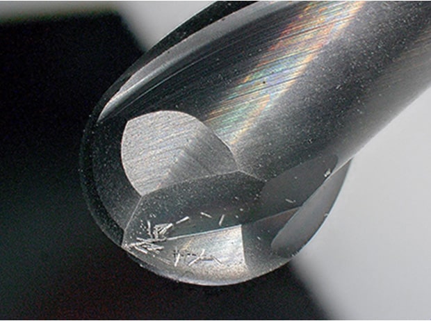
Observation of drill wear
50×, ring illumination
3D image
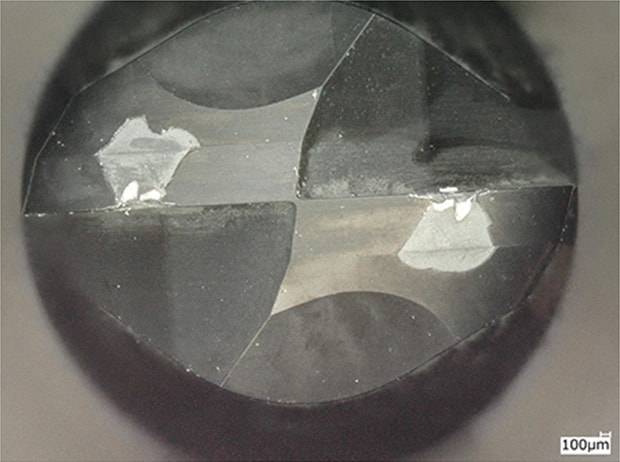
200×, ring illumination
Observation of edge wear
1000×, coaxial illumination
Observation of edge wear
300×, multi-lighting
Observation of edge wear, 3D comparison image
150×, ring illumination
Observation of chip adhesion
30×, ring illumination
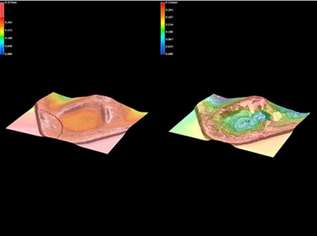
Observation of edge adhesion
3D observation showed that what was thought to be chipping was actually adhesion.
Low magnification at 50×, ring illumination
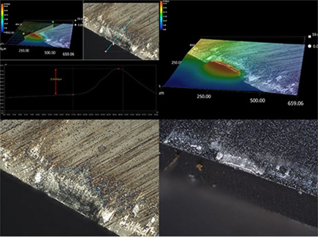
3D image at 500×, coaxial illumination
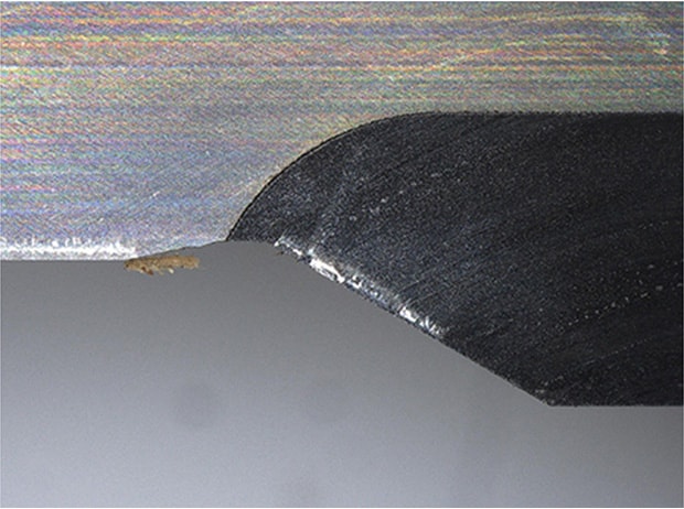
Observation of the point at which the tool started to break
Multi-lighting allows easy observation of the starting point of a fracture surface.
20×, multi-lighting
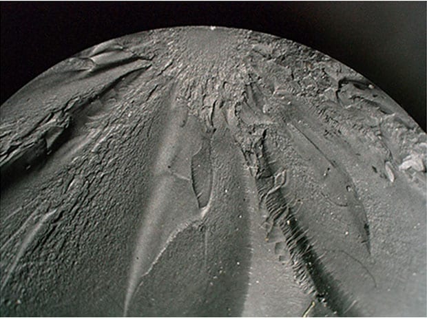
30×, multi-lighting
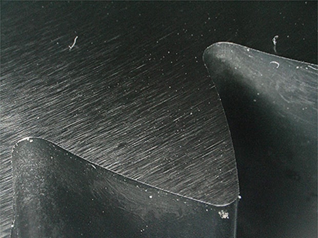
Observation of a cut surface
Optical Shadow Effect Mode allows for observation of waves on a cut surface, which is conventionally only possible by using an interferometer, in just a few seconds.
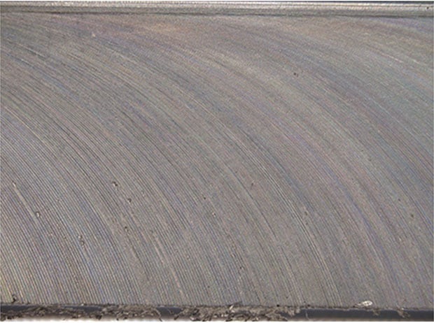
20×, ring illumination
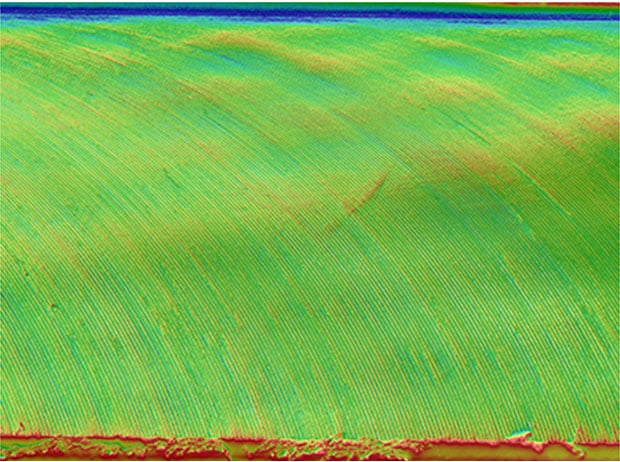
Optical Shadow Effect Mode image
Get detailed information on our products by downloading our catalog.
View Catalog