2D/3D Laser Profiler
LJ-X8000 series
Specs 2D/3D Laser Profiler LJ-X8000 series
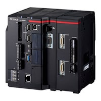
Controller
|
Model |
LJ-X8000E*1 |
LJ-X8002 |
|||
|
Image |
|
|
|||
|
Head input |
Up to 2 head units |
||||
|
Sampling cycle (trigger interval) |
[2D mode] Maximum speed of 1 kHz (1 ms) *2 |
[2D mode] Maximum speed of 1 kHz (1 ms) *2 |
|||
|
Number of registered inspection settings |
Up to 1000 (depending on SD card capacity and setting contents) for each of SD cards 1 and 2. External switching is possible |
||||
|
Master profile / number of reference images |
Maximum 200 per setting per head (depends on SD card capacity) |
[2D mode]Maximum 200 per setting per head (depends on SD card capacity) |
|||
|
Memory card |
• SD card slot × 2 |
||||
|
Number of tools |
100/setting (of those, 20 are for misalignment correction) |
[2D mode]100/setting (of those, 20 are for misalignment correction) |
|||
|
Interface |
Control input |
20 points (input terminal block: 5 points, parallel I/O: 15 points) |
|||
|
Control output |
28 points (output terminal block: 6 points, parallel I/O: 22 points) |
||||
|
RS-232C |
• Value output and control I/O (exclusive use with PLC link using an RS-232C port) |
||||
|
PLC link |
• Value output using Ethernet port or RS-232C port, and control I/O |
||||
|
Ethernet |
• Value output and control I/O |
||||
|
USB |
• Can output values (3D mode only), upload/download inspection settings, perform various simulations, send/receive various data including profile and image data, and be used with remote connection programs via KEYENCE PC application software |
||||
|
EtherNet/IP™ |
• Can input/output numerical values and perform control I/O using the Ethernet port or the optional EtherNet/IP™ unit CB-NEP20E (Cannot be used with PLC Link, PROFINET, and EtherCAT®) |
||||
|
PROFINET |
• Can input/output numerical values and perform control I/O using the Ethernet port or the optional PROFINET unit CB-NPN20EA (Cannot be used with PLC Link, EtherNet/IP, and EtherCAT®) |
||||
|
EtherCAT® |
• Can output numerical values and perform control I/O by connecting the optional EtherCAT® unit CB-NEC20E (Cannot be used with PLC link, EtherNet/IP™, and PROFINET) |
||||
|
Mouse |
Various menus can be controlled via the dedicated mouse (included with the controller) |
||||
|
SNTP |
Automatic correction of date and time for this unit is possible by connecting to an SNTP server |
||||
|
USB HDD |
By connecting an HDD (max. 2 TB) to the dedicated USB port (supports USB 3.0, |
||||
|
Monitor output |
Analog RGB output, XGA 1024 × 768 (24-bit color, 60 Hz) |
||||
|
Encoder input |
1 port: combination RS-422 line-driver output (with 5 V output: maximum 150 mA) open collector output (compatible with 5 V, 12 V, 24 V) |
||||
|
Response frequency |
RS-422 |
Single phase / Z phase: 1.6 MHz, 2 phase / 1x: 1.6 MHz, 2 phase / 2x: 3.2 MHz, 2 phase / 4x: 6.4 MHz |
|||
|
Open collector (OC) |
Single phase / Z phase: 100 kHz, 2 phase / 1x: 100 kHz, 2 phase / 2x: 200 kHz, 2 phase / 4x: 400 kHz |
||||
|
Laser ON input |
Non-voltage input (Shorted with short pin when shipped from factory) |
||||
|
Cooling fan |
Provided |
||||
|
Minimum display unit |
0.1 µm 0.000004", 0.01°, 0.00001 mm2 |
[2D mode]0.1 µm 0.000004", 0.01°, 0.00001 mm2 |
|||
|
Language |
Switchable between English, Japanese, Simplified Chinese, Traditional Chinese, Korean, German, French, Italian, Thai, Czech, Hungarian, and Polish |
||||
|
Ratings |
Power voltage |
24 V DC ±10% |
|||
|
Maximum current consumption |
3.3 A |
||||
|
Environmental resistance |
Ambient temperature |
0 to +45°C 32 to +113°F (DIN rail mounting) / 0 to +40°C 32 to +104°F (base surface mounting) |
|||
|
Relative humidity |
85% RH or less (no condensation) |
||||
|
Weight |
Approx. 2500 g |
||||
|
*1 3D mode cannot be used with the LJ-X8000E. |
|||||
Controller
|
Model |
LJ-X8000A |
|||
|
Image |
|
|||
|
Head input |
Up to 1 head |
|||
|
Sampling cycle (trigger interval) |
When connecting the LJ-X8000 Series: maximum speed of 16 kHz (63 μs) *1 |
|||
|
Interface |
Control input |
Supports the batch measurement start (MEASURE_START) and batch measurement stop (MEASURE_STOP). |
||
|
Control output |
•Supports the trigger ready (READY) and system error (ERROR). |
|||
|
Synchronous input / output |
For trigger synchronization of multiple controllers*5 |
|||
|
Ethernet |
Supports the profile output, setting, controll, 1000BASE-T/100BASE-TX*6 |
|||
|
Encoder input |
One system |
|||
|
Response frequency |
RS-422 |
Single phase/Z-phase : 1.6 MHz |
||
|
Open collector (OC) |
Single phase/Z-phase : 100 kHz |
|||
|
Laser ON input |
Non-voltage Input (a short circuit via the short pin at the time of shipment from the factory) |
|||
|
Ratings |
Power voltage |
24 VDC±10% |
||
|
Maximum current consumption |
1.3A |
|||
|
Environmental resistance |
Ambient temperature |
0 to + 45 °C (DIN rail mounting) / 0 to + 40 °C (side mounting) |
||
|
Relative humidity |
85% RH or less (no condensation) |
|||
|
Weight |
Approx. 700 g |
|||
|
*1 When the measurement range is narrowed in accordance with the binning settings. |
||||
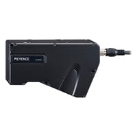
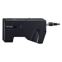
head
|
Model |
LJ-X8020 |
LJ-X8060 |
LJ-X8080 |
LJ-X8200 |
LJ-X8300 |
LJ-X8400 |
LJ-X8900 |
|||
|
Image |
|
|
|
|
|
|
|
|||
|
Reference distance |
20 mm 0.79" |
64 mm 2.52" |
73 mm 2.87" |
245 mm 9.65" |
288 mm 11.34" |
380 mm 14.96" |
980 mm 38.58" |
|||
|
Measurement range |
Z-axis (height) |
±2.2 mm 0.09" (F.S.=4.4 mm 0.17") |
±7.3 mm 0.29" (F.S.=14.6 mm 0.57") |
±20.5 mm 0.81" (F.S.=41 mm 1.61") |
±34 mm 1.34" (F.S.=68 mm 2.68") |
±53 mm 2.09" (F.S.=106 mm 4.17") |
±60 mm ±2.36" (+95 to -220 mm +3.74" to -8.66" *12) (F.S.=315 mm 12.40") |
±400 mm 15.75" (F.S.=800 mm 31.50") |
||
|
X-axis (width) |
NEAR side |
7 mm 0.28" |
15 mm 0.59" |
30 mm 1.18" |
64 mm 2.52" |
134 mm 5.28" |
180 mm 7.09" (163 mm 6.42" *12) |
300 mm 11.81" |
||
|
Reference distance |
7.5 mm 0.30" |
16 mm 0.63" |
35 mm 1.38" |
72 mm 2.83" |
150 mm 5.91" |
210 mm 8.27" |
510 mm 20.08" |
|||
|
FAR side |
8 mm 0.31" |
39 mm 1.54" |
80 mm 3.15" |
160 mm 6.30" |
240 mm 9.45" (320 mm 12.60" *12) |
720 mm 28.35" |
||||
|
Light source |
Blue semiconductor laser |
|||||||||
|
Light source |
Wavelength |
405 nm (visible light) |
||||||||
|
Laser class |
Class 2M laser product (IEC60825-1, FDA (CDRH) Part 1040.10 *1) *2 |
|||||||||
|
Output |
10 mW |
|||||||||
|
Spot size |
Approx. 16 mm × 32 μm 0.63" × 0.0013" (reference distance) |
Approx. 25 mm × 49 μm 0.98" × 0.0019" (reference distance) |
Approx. 44 mm × 72 μm 1.73" × 0.0028" (reference distance) |
Approx. 115 mm × 116 μm 4.53" × 0.0046" (reference distance) |
Approx. 215 mm × 108 μm 8.46" × 0.0042" (reference distance) |
Approx. 275 mm × 249 μm 10.83" × 0.0098" (reference distance) |
Approx. 622 mm × 566 μm 24.49" × 0.0223" (reference distance) |
|||
|
Repeatability |
Z-axis (height) |
0.3 μm 0.000012" *3*4 |
0.4 μm 0.000016" *3*4 |
0.5 μm 0.000020" *3*4 |
1 μm 0.000039" *3*4 |
3 μm 0.000118" *3*4 |
5 μm 0.000197" *3*4 |
10 μm 0.0004" *3*4 |
||
|
X-axis (width) |
0.3 μm 0.000012" *3*5 |
0.5 μm 0.000020" *3*5 |
1.0 μm 0.000039" *3*5 |
3 μm 0.000118" *3*5 |
5 μm 0.000197" *3*5 |
10 μm 0.0004" *3*5 |
25 μm 0.0010" *3*5 |
|||
|
Linearity |
Z-axis (height) |
±0.05% of F.S. (±0.012%) *6 |
±0.04% of F.S. (±0.008%) *6 |
±0.03% of F.S. (±0.004%) *6 |
±0.04% of F.S. (±0.006%) *6 |
±0.033% of F.S. (±0.005%) *6 |
Reference distance: ±60 mm ±2.36" ±0.025% of F.S. (±0.003%) |
Near~reference: distance ±0.015% of F.S. (±0.004%) |
||
|
Profile data interval |
X-axis (width) |
2.5 μm 0.000098" (2 μm 0.000079"~) *7 |
5 μm 0.000197" (4 μm 0.000157"~) *7 |
12.5 μm 0.0005" (10 μm 0.0004"~) *7 |
25 μm 0.0010" (20 μm 0.0008"~) *7 |
50 μm 0.0020" (40 μm 0.0016"~) *7 |
75 μm 0.0030" (50 μm 0.0020"~) |
225 μm 0.0089" (100 μm 0.0039"~) *7 |
||
|
Profile data count |
3200 points |
|||||||||
|
HDR (high dynamic range) |
Single-shot HDR *8 |
|||||||||
|
Laser irradiation position confirmation function |
Light source |
Blue LED (405 nm) |
||||||||
|
Temperature characteristic |
0.01% of F.S./°C |
|||||||||
|
Environmental resistance |
Enclosure rating |
IP67 (IEC60529) *9 |
||||||||
|
Ambient light |
Incandescent lamp: 10,000 lux or less *10 |
|||||||||
|
Ambient temperature |
0 to +45°C 32 to +113°F *11 |
|||||||||
|
Relative humidity |
85% RH or less (no condensation) |
|||||||||
|
Vibration resistance |
10 to 57 Hz, double amplitude 1.5 mm 0.06"; 3 hours each for X, Y, and Z axes |
|||||||||
|
Shock resistance |
15 G / 6 msec |
|||||||||
|
Material |
Aluminum |
|||||||||
|
Weight |
Approx. 1000 g 2.20 lb |
Approx. 1100 g 2.43 lb |
Approx. 1200 g 2.65 lb |
Approx. 1400 g 3.09 lb |
Approx. 1300 g 2.87 lb |
Approx. 1600 g 3.53 lb |
||||
|
*1 Classification performed based on IEC60825-1 in accordance with FDA (CDRH) Laser Notice. |
||||||||||


