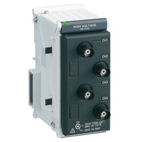
Multi-input Data Logger
NR-X series
High-speed, high-voltage measurement unit NR-HV04

*Please note that accessories depicted in the image are for illustrative purposes only and may not be included with the product.
Specifications
Model | NR-HV04 *1 | |||
Type | High-speed, high-voltage measurement unit | |||
Input method | Insulated single-end input, channels insulated from each other, input channels insulated from other units (PC) | |||
Number of channels | 4 ch *2 | |||
Measurement cycle | Maximum sampling cycle: 1 μs (1 MHz) to 60 s | |||
A/D converting system | Successive approximation, simultaneous sampling of all channels | |||
A/D resolution | 14 bit | |||
Input frequency band | 250 kHz (−3 dB or more) | |||
Input type | ±1000 V, ±500 V, ±200 V, ±100 V, ±50 V, ±20 V, ±10 V, ±5 V, ±2 V | |||
Low pass filter | PASS, 7 Hz, 500 Hz, 50 kHz (−12 dB/oct) | |||
Maximum input voltage | [When using OP-35409 1:1 voltage-resistant probe] 1000 V peak and 700 Vrms, or 700 VDC; | |||
Digital filter | Averaging rate: 1 to 128 (automatically selected) | |||
Withstand voltage | Input to system bus/earth | 2200 VAC (50/60 Hz) for 1 minute | ||
Connector format | Insulated BNC connector | |||
Input impedance | 1 MΩ ±1%, approx. 30 pF | |||
Input coupling | AC/DC/AC-RMS/DC-RMS | |||
Measurable range | ±1000 V: −1000.00 to +1000.00 V | |||
Measurement accuracy | ±0.1% of F.S. | |||
Display resolution | ±1000 V: 50 mV | |||
Buffer memory | 16M data*4 | |||
Warm up time | 30 minutes or more | |||
RMS measurement function | Number of channels | 4 ch | ||
Maximum allowable voltage to ground | [When using OP-35409 1:1 voltage-resistant probe] Measurement terminal, GND terminal: 300 Vrms (CAT II); | |||
RMS measurement function | Accuracy | Sine wave: 20 Hz to 1 kHz, ±0.5% of F.S.; 1 to 20 kHz, ±1.5% of F.S.; Crest factor: 4 or less; Response time: 500 ms | ||
Residual noise level | 0.01% of F.S., LPF: 500 Hz (200 μs/S, digital filter: ON) (typ.); 0.05% of F.S., LPF: PASS (typ.) | |||
Calculationfunction | CH1 to CH2, CH3 to CH4 (Single-channel usage not possible when using the calculation function) | |||
Common mode noise reduction ratio | 80 dB or more (at max. 60 Hz DC) (typ.) | |||
Rating | Power consumption | 3 W or less | ||
Environmental resistance | Insulation resistance | 500 VDC, 10 MΩ or more | ||
Ambient temperature | 0 to +40°C 32°F to 104°F | |||
Relative humidity | 10 to 85% RH (no condensation) | |||
Weight | Approx. 270 g 9.53 oz | |||
*1 The above specifications are the values when zero point adjustment is performed after the warm-up period in an environment with a temperature of 23°C ±3°C 73.4°F ±5.4°F. | ||||


