Data Acquisition (DAQ)
How to Measure Voltage
Voltage, for our purposes, can be measured in two ways—measuring the analog voltage output from a sensor and measuring the power voltage—each of which is explained in this section.
AC Voltage versus DC Voltage
Before we explain how to measure voltage in an AC circuit, we must explain the concept of AC current, which differs significantly from DC. Alternating current voltage (AC) is a type of electrical voltage where the flow of electric charge periodically reverses direction, going to its peak value, then dropping down through zero to a negative peak value, and then returning to zero, completing one cycle.
In the US, this process happens 60 times per second (basically 60Hz), and you’re usually measuring the RMS (Root Mean Square) value of the AC voltage. Since it fluctuates below zero value, the measurement technique differs significantly.
Measuring DC Voltage
When measuring DC voltage, you need to keep the probe polarity in mind. Suppose you’re measuring a 5V source; switching probe polarities would result in a wrongful reading of -5V. This is commonplace, as you’re comparing the positive end to the ground reference point, which is 0V, and a negative reading is a perfectly normal indication that the probes are reversed in polarity.
Measuring AC Voltage
However, this doesn’t happen when we’re measuring AC voltage, where the value fluctuates from a positive peak to a negative one concerning the neutral, which is a reference point of 0V. Instead of measuring polarity, you’re measuring an effective value of AC voltage concerning neutral.
Thus, the polarity of the probes in AC voltage measurements doesn’t matter. Just connect the probes parallel to the source or the load, and you should get a reading of the AC voltage. However, it’s important to note that AC and DC voltages are fundamentally different in their behavior, so you should always select the appropriate voltage type and range when conducting measurements.
Some high-quality measuring systems have a built-in detection circuit, automatically detecting the type and range of voltage you’re measuring.
Measuring the Analog Voltage Output From a Sensor

The output voltage device can be measured by connecting + and − from the target analog voltage output circuit directly into a voltage input measuring instrument.
Measuring the Power Voltage

The voltage can be measured by connecting probes to the + and − terminals of the target voltage.
Triggers
Accurate measurement and logging of signals requires that the start points used to acquire data be consistent. These start points are called “triggers.”
Setting Triggers
In actual measurement, it is important to set triggers to collect target waveforms.
In general, the following two types of triggers are used for measurement.
- Rising rigger: Measurement is triggered when the voltage changes in the positive direction and exceeds the specified voltage.
- Falling trigger: Measurement is triggered when the voltage changes in the negative direction and falls below the specified voltage.
When using triggers, set the number of sampling points so that the target waveforms are included. To check the conditions before and after the target phenomenon, set pre-triggers.

Rising Trigger
A rising trigger is a threshold value that starts the measurement process and data logging or acquisition once the signal voltage passes the pre-set value. It’s typically used to stabilize a repeating signal, as it enables the measuring system to begin voltage measurement each time the signal waveforms and each time the signal crosses the aforementioned value while going up.
This is particularly useful in applications where you need to observe a signal rising from low-to-high transitions.

Falling Trigger
A falling trigger is the opposite of a rising trigger. The measuring unit will only capture data once the signal voltage drops below a previously set value. This is how to measure voltage in applications where high-to-low voltage transitions are of interest, like digital circuits where a falling edge might signify a particular operation.
Falling triggers are often used in digital electronics, especially for analyzing clock pulses and reset signals.
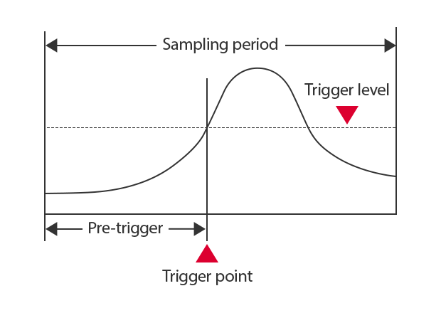
Pre-trigger
A pre-trigger is a feature that allows the measuring system to capture data before the trigger event occurs, which is particularly useful for analyzing signal behaviors that occur before specific events, such as voltage spikes or drops. This is invaluable for troubleshooting and understanding complex electronic behaviors.
Looking to take your voltage measurements to the next level? Contact KEYENCE today!
![Introductory Guide to Voltage Measurement [Basic Knowledge of Voltage Measurement]](/img/asset/AS_118629_L.jpg)
Related Products
Industries
- Temperature Measurement for the Electronic Device Industry
- Temperature Measurement for the Electrical Equipment Industry
- Temperature Measurement for the Metal and Steel Industry
- Temperature Measurement for Plastics Industry
- Voltage Measurement for the Automotive Manufacturing Industry
- Voltage Measurement for Electric Vehicle Industry
- Voltage Measurement for Plastic and Metal Industry