A Solution to Problems in Deformation Measurement after Heat Treatment
Generally speaking, heat treatment is a process that applies heat to materials or products. Heat treatment includes the processing of metal materials by heating, as well as heat sterilization of foods and other products. This section examines deformation of metal resulting from the heat treatment process. While the deformation resulting from heat treatment can be simple, such as compression or warpage in the case of square beams and rods, three-dimensional deformation can occur in products that have complex shapes. This requires advanced technologies for measuring these shapes.
This page explains basic knowledge of deformation caused by heat treatments that are used with iron or steel materials to control their structures and improve their properties. It also covers issues with measuring deformation and some possible solutions.
- Metal Heat Treatment
- Examples of Deformation Caused by Heat Treatment (Volume Change due to Phase Transformation)
- Measures to Prevent Deformation Problems Caused by Heat Treatment
- Problems in Conventional Deformation Measurement after Heat Treatment
- Solution to Problems in Deformation Measurement after Heat Treatment
- Summary: Dramatic Improvements for Measuring Deformation after Heat Treatment
Metal Heat Treatment
Heat treatment of metals is a processing technique which heats and cools a metal in order to change its properties without changing its shape. Some of the properties to be modified include strength, hardness, toughness, impact resistance, wear resistance, corrosion resistance, machining properties, and cold workability.
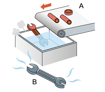
- A
- Heating (until metal turns red)
- B
- Cooling (until heated metal turns black)
Examples of Deformation Caused by Heat Treatment (Volume Change due to Phase Transformation)
There are multiple heat treatment methods including quenching, tempering, annealing, and normalizing. During these processes, a phenomenon known as phase transformation occurs.
Phase transformation is a process that occurs during heat treatment when a metal changes from a solid to a liquid and then changes again from a liquid to a solid. This occurs because the current form (structure) of the metal changes when its crystal lattice changes as a result of the temperature. When the structure changes during phase transformation, the volume also changes, causing deformation.
For example, when a eutectoid steel, which is a steel containing approximately 0.8% carbon, is heated from room temperature to create an austenite structure and then cooled, it deforms due to the structure change. The structure after phase transformation varies depending on the cooling method, and therefore the cooling method also affects the amount of deformation.
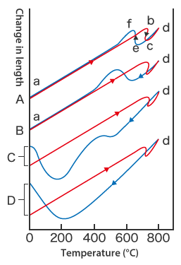
This graph shows the differences in deformation resulting from different cooling methods.
In the case of A, the metal expands as a result of heating (a → b), and changes in its dimensions due to phase transformation can be seen at approximately 750°C (1382℉) during heating (b → c) and at approximately 730°C (1346℉) during cooling (e → f).
In C (oil cooling) and D (water cooling), there is a clear change in length after cooling.
- A: Furnace cooling (slow cooling)
- The metal is kept in the furnace after heating and cools while inside the furnace. This method cools the metal at a speed of approximately 30°C (54℉) per hour. The structure after phase transformation is pearlite.
- B: Air cooling
- The metal is removed from the furnace after heating and cools at room temperature. The structure after phase transformation is sorbite.
- C: Oil cooling
- The heated metal is cooled in oil. Typically, metal is cooled in oil at approximately 60 to 80°C (140 to 176℉). In the structure after phase transformation, part of the austenite structure is transformed to troostite.
- D: Water cooling
- The metal is cooled in water at approximately 40°C (104℉). The structure after phase transformation is martensite.
Measures to Prevent Deformation Problems Caused by Heat Treatment
In addition to the phase transformation described in the previous section, other reasons for deformation problems caused by heat treatment include incorrect or uneven surface shape or heating/cooling. This section explains these deformation problems, their causes, and measures to prevent them.
Quenching cracks
This is a problem in which material cracking occurs. It can occur on the day following quenching or later after the material was cooled to approximately 200°C (392℉) or below.
- Causes:
- Possible causes include shape defects caused by volume expansion due to uneven heating or cooling, inappropriate tempering immediately after quenching, and excessively high quenching temperature.
- Countermeasures:
-
- Review the product shape and surface conditions.
- Do not cool quenched materials to approximately 200°C (392℉) or below.
- Perform tempering of materials immediately after quenching.
- Lower the quenching temperature.
Grinding cracks
This is a problem in which cracking of the steel material occurs when it is ground after heat treatment. There are two types of grinding cracks: Type 1 grinding cracks which occur when a surface machined by cutting, polishing, or other method reaches approximately 100°C (212℉), and Type 2 grinding cracks which occur when a surface machined by cutting, polishing, or other method reaches approximately 300°C (572℉).
-

Type 1 grinding crack
-

Type 2 grinding crack
- Causes:
- Residual austenite expands when it transforms into martensite. Stress caused by this expansion causes cracking of the material. This deformation can also occur when a surface machined by cutting, polishing, or other method reaches approximately 650 to 850°C (1202 to 1562℉ ).
- Countermeasures:
-
- Perform appropriate tempering.
- Reduce the heat generated by grinding friction.
Quenching deformation
There are two types of steel deformation caused by heat treatment: thermal deformation caused by thermal expansion or contraction during quenching or tempering, and a change in volume caused by phase transformation.
- Causes:
- This deformation occurs as a result of uneven heating or cooling, rapid heating or cooling, or parts with uneven thickness. When a material has a complex shape, an uneven distribution of temperature in the material can also cause this deformation.
- Countermeasures:
-
- Review the shape so that the product can be heated and cooled evenly.
- Reduce the heating and cooling speeds.
Problems in Conventional Deformation Measurement after Heat Treatment
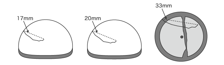
It is extremely important to verify that the dimensions and shapes after heat treatment are within tolerances. Products having complex shapes in particular require high-accuracy, quantitative 3D shape measurement.
Conventional deformation measurement after heat treatment uses profile measurement systems or coordinate measuring machines. However there are various problems in measurement using a conventional coordinate measuring machine or profile measurement system. These include the high level of difficulty required to obtain accurate measurements, and variation in the measured values.
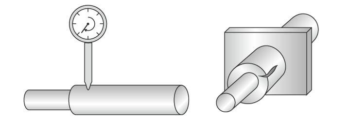
Problems in deformation measurement using a profile measurement system
A profile measurement system measures and records the profile of a target by tracing its surface with a stylus. In recent years, profile measurement systems have been developed that use a laser instead of a stylus to measure complex shapes by tracing the profile in a non-contact manner. Some models are even able to perform measurement of both the top and bottom surfaces.
However with a profile measurement system, it is necessary to acquire accurate measurement lines for the measurement points.
This involves the following problems.
- Measurement work requires much time, including time for fastening the sample to the jig and leveling it. Knowledge and skills related to using profile measurement systems are also required in order to level a target accurately.
- The stylus of a profile measurement system moves up and down in an arc centered on the fulcrum of the stylus arm, and the tip of the stylus also moves in the X-axis direction. This produces error in the X-axis data.
- Tracing the desired line with the stylus is extremely difficult work, and even slight displacement of the stylus produces error in the measured values.
- It is also difficult to increase the number of targets because of the need to pinpoint specific locations for measurement.
- Only part of a target can be measured, and evaluation of the entire surface is not possible.
Problems in deformation measurement using a coordinate measuring machine
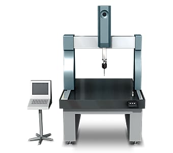
Typical coordinate measuring machines use a probe to scan or trace across a surface, gathering multiple points of data at a specified pitch.
This measurement method involves the following problems.
- Ensuring that the probe moves as intended is an extremely difficult task, particularly for straight lines along the center of a cylinder or curved surface, or lines passing through the center of a circle. If a fillet or round has a wide center angle, then because the entire circle is calculated based on a short arc, even a small error in measurement will become largely magnified. Such deviations in the measurement points can result in slight variation in the measured values.
- When measuring a small 3D shape, the probe may be unable to contact the measurement positions. Because measurement accuracy is proportional to the number of points or lines that are measured, it is necessary to measure a large number of points or lines.
In this way, measurement using a coordinate measuring machine involves significant problems, including the fact that not all workplace operators can accurately measure shapes, the existence of parts that cannot be measured at all, and limited locations where the machine can be installed.
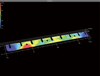
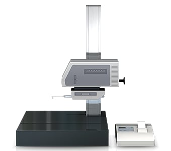
Solution to Problems in Deformation Measurement after Heat Treatment
These measuring instruments can run into issues with the positioning of an object or probe tip, and can struggle with providing overall measurement data of a 3D surface since they are simply measuring by points or lines. To resolve these problems, KEYENCE has developed the VR Series 3D Optical Profilometer.
The VR Series accurately captures the 3D shape of the entire target surface in as little as one second and without contacting the target. It is capable of instantly and accurately quantifying an entire 3D surface with no measurement errors. This section introduces some specific advantages of the VR Series.
Advantage 1: Measure a large number of points in as little as one second
The VR Series acquires surface data (800,000 points) for the 3D target shape in as little as one second, dramatically reducing the time required for measuring large numbers of points. It accurately and instantaneously measures the maximum and minimum irregularities on the entire target surface, enabling rapid evaluation of all locations on the target based on the preset tolerances.
Once a workpiece has been scanned, its profile (cross-section) can also be measured at locations different from the locations used in past measurement. This eliminates the need to set and measure the same target again.

Advantage 2: Measurement data can be compared with reference data
The VR Series is capable of more than just efficiently collecting data. Measurement data can be displayed in a list, and the same analysis contents can be applied to all data at the same time.
It is possible to quickly check the differences in data obtained by measuring multiple target shapes before and after heat treatment, and the amount of difference in bad products when compared to the reference product. This enables easy quantitative analysis and evaluation of deformation caused by heat treatment.
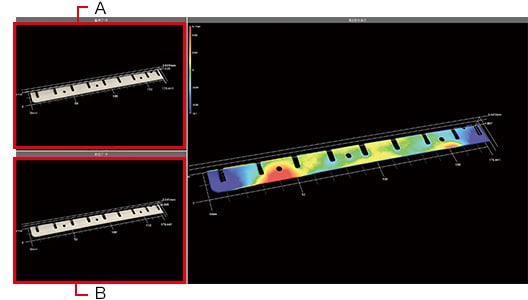
- A
- Reference data
- B
- Measurement data
The VR Series can quicky measure targets that have complex shapes, something that would have previously required a lot of time and labor. Not only is data quickly captured but all the measurement results are digitalized, significantly reducing the work required for data comparison and analysis.
Summary: Dramatic Improvements for Measuring Deformation after Heat Treatment
Previously, measuring deformation caused by heat treatment took a lot of time, limiting the number of samples that could be measured. In some cases, measurement was not possible at all due to the complex shape of the part. However, the VR Series is capable of quickly measuring and quantifying deformation for these shapes. As a result, the VR Series can evaluate product quality with a higher level of accuracy and efficiency.
- Significantly reduce the time spent measuring complex shapes by capturing entire surface data simultaneously.
- Various differences in deformation can be easily identified and analyzed by capturing and comparing multiple sets of measurement data.
- True quantitative measurement is possible, eliminating variation in results due to human error.
- Simply place the target on the stage and click a button to capture accurate data, eliminating the need for specialized operators since there is no need for positioning or other preparation.
- Accurately measure a lot targets in a short amount of time with high-speed scanning.
The VR Series is also capable of comparing data to previous scans and CAD models, as well as analyzing roughness.

